



| AI Summary |
| A CNC press brake is a sheet metal bending machine that utilizes computer-controlled axes, precision tooling, and backgauges to bend flat blanks into specific angles and flange dimensions. |
| The 7-step programming workflow includes: entering part geometry (or DXF import), tooling selection, bend sequencing, tonnage/speed calculation, backgauge setup, springback compensation, and a first-article inspection run. |
| Critical safety and precision rules require that the V-die opening matches material thickness (6× to 12× T), the punch tip radius prevents cracking (r ≥ T), and calculated tonnage never exceeds 80% of machine capacity. |
| Typical programming mistakes—such as ignoring material springback, choosing incorrect V-widths, or neglecting 3D collision simulations—result in out-of-tolerance dimensions, scrap parts, or severe machine overload. |
Introduction: Why CNC Press Brake Programming Skills Matter
A CNC press brake is only as productive as the operator who programs it. The machine may have a Delem DA-69T controller, servo-electric drives, and laser angle measurement – but if the bending program is incorrectly set up, the result is scrap parts, broken tooling, or in extreme cases, machine damage.
This step-by-step programming guide is written for operators with basic CNC knowledge who want to confidently program a CNC press brake for standard sheet metal bending jobs. It covers everything from reading the part drawing to running a successful first article.
What You Need Before Programming
Before you start programming, gather the following:
- Part drawing or DXF file with all bend dimensions, angles, and tolerances
- Material specification: grade, thickness, and yield strength (Rp0.2)
- Tooling inventory: available punch tip radii, V-die openings, and lengths
- Machine capability data: maximum tonnage, working length, and stroke depth
- Springback compensation values for your material (from your reference table or the controller’s material database)
Step 1: Enter or Import the Part Geometry
Manual Entry
On the CNC controller (e.g., Delem DA-66T), navigate to the Part Program screen. Enter:
- Flange lengths for each bend (L1, L2, L3… in mm)
- Bend angles for each bend (e.g., 90°, 135°, 45°)
- Bend direction (positive = upward bend, negative = downward bend)
- Material thickness (T in mm)
- Material type (mild steel, SS, aluminium – from the controller’s material library)
DXF Import (Offline Programming)
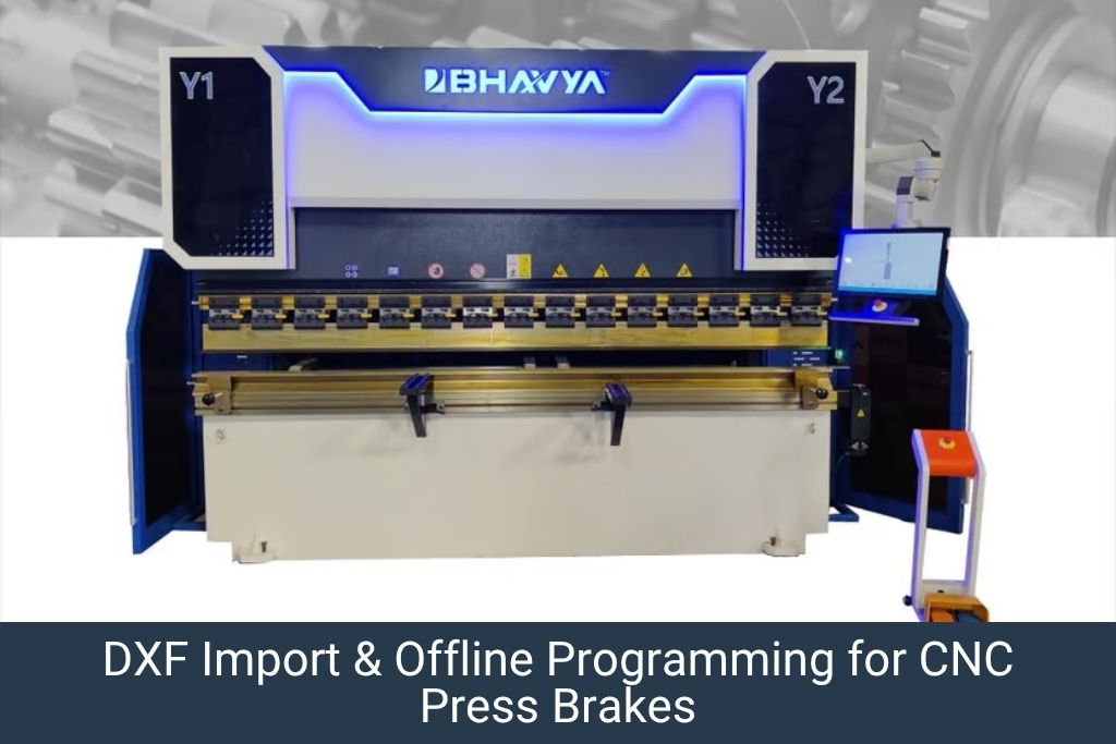
Most modern CNC press brakes support DXF import via USB or network. The CAM module reads the 2D flat blank development and automatically:
- Identifies all bend lines and their positions
- Calculates flange lengths based on the bend allowance for the material and tooling selected
- Suggests a bend sequence based on collision avoidance algorithms
Always verify the imported geometry against the original drawing before proceeding. Check that bend radii and allowances match your selected tooling.
Step 2: Select Tooling (Punch & Die)
Tooling selection is one of the most important programming steps. The wrong tooling selection leads to:
- Incorrect bend radius in the finished part (punch tip radius determines the inner bend radius)
- Insufficient tonnage (die too narrow for material thickness)
- Tooling collision with previous bends (insufficient throat depth)
V-Die Opening (V-Width) Selection Rule
The standard rule for V-die opening: V-width = 6× to 10× material thickness for mild steel; 8× to 12× for stainless steel; 6× to 8× for aluminium.
| Material Thickness (mm) | Recommended V-Width (mm) | Expected Inner Radius (mm) |
| 1.0 | 6-8 | 1.0-1.5 |
| 1.5 | 10-12 | 1.5-2.0 |
| 2.0 | 12-16 | 2.0-2.5 |
| 3.0 | 18-22 | 3.0-3.5 |
| 4.0 | 25-30 | 4.0-5.0 |
| 5.0 | 30-35 | 5.0-6.0 |
| 6.0 | 35-45 | 6.0-8.0 |
Punch Tip Radius Selection
The punch tip radius (r) determines the inner radius of the bent part. Select a punch tip radius equal to the specified inner bend radius in the drawing. As a minimum, the punch tip radius should not be less than the material thickness (r ≥ T) to prevent cracking.
Our Other Product
NC Front Cylinder Hydraulic Press Brake Machine (NCF Series)Step 3: Calculate Bend Sequence
The bend sequence is the order in which each bend is made. A correct sequence:
- Prevents part-to-tooling collisions during bending
- Allows all flanges to be reached by the backgauge
- Minimises part handling and repositioning time
General Bend Sequence Rules
- Start with internal bends (closest to the part centre) and work outward.
- Make the shortest flange last if it causes collision risk.
- For box shapes, make opposite bends before adjacent bends.
- Use the controller’s graphical simulation to verify no collision occurs in the planned sequence.
Most modern Delem and ESA controllers have an automatic bend sequence optimiser that generates a collision-free sequence automatically. Always verify this with the 3D graphical simulation before running the part.
Step 4: Set Tonnage and Bending Speed Parameters
Tonnage Calculation
The required bending tonnage for air bending is calculated using the formula:
P = (C × T² × L × Rm) / V
Where: P = Bending force (kN), C = Constant (1.42 for air bending), T = Material thickness (mm), L = Part length being bent (mm), Rm = Ultimate tensile strength (MPa), V = V-die opening width (mm)
Most CNC controllers calculate this automatically when you enter material type, thickness, length, and die selection. Always ensure the calculated tonnage is below 80% of the machine’s maximum rated tonnage to maintain a safety margin and protect tooling.
| Material | Rm (MPa) | Tonnage factor vs Mild Steel |
| Mild Steel (CRCA) | 400 | 1.0× |
| High Strength Steel (S355) | 490 | 1.2× |
| Stainless Steel 304 | 620 | 1.5× |
| Stainless Steel 316 | 580 | 1.4× |
| Aluminium 5052 | 230 | 0.6× |
| Copper (soft) | 200 | 0.5× |
Speed Parameters
Typical CNC press brake speed settings:
- Fast approach speed (above material): 100-200 mm/s
- Bending speed (during material deformation): 5-20 mm/s – slower for thicker/harder materials
- Decompression speed (after bend): 2-5 mm/s – critical to prevent springback shock
- Return speed: 100-200 mm/s
What Our Customers Say
“Our production speed has improved ever since we got a Bhavya machine. It’s smooth, durable, and works exactly as promised.”
Arti Mishra On Google
Step 5: Set Backgauge Position for Each Bend
The backgauge positions the sheet to achieve the correct flange length. The backgauge X-position for each bend is calculated as:
X = Flange length − (V/2) + BA/2
Where: X = Backgauge position from centreline of die, V = V-die opening, BA = Bend allowance for material and angle
The CNC controller calculates this automatically based on the entered flange length, material, and tooling. However, always verify on the first piece by measuring the actual flange length and correcting the X-offset in the program if needed.
Multi-Gauge Backgauge Setup
For parts with multiple bends, the controller stores a separate backgauge position for each bend step. During bending, the backgauge moves automatically between positions as the operator progresses through the bend sequence. Verify that the backgauge reaches each position correctly before running production.
Step 6: Set Angle Compensation (Springback Correction)
Enter the springback compensation for your material in the controller’s material setup screen. As a starting guide:
- Mild steel (CRCA), 2mm thick, 90° air bend: +1°-2° overbend
- Stainless steel 304, 2mm, 90° air bend: +2°-4° overbend
- Aluminium 5052, 2mm, 90° air bend: +1°-3° overbend
Use the machine’s automatic angle measurement system (laser or camera-based, if equipped) to measure the actual angle after the first bend and automatically update the compensation value. This eliminates the need for manual springback tables over time.
 Email Us Now!
Step 7: Run First Article & Inspect
The first-article run is the most critical step. For each new program:
- Load a test piece from the production batch material.
- Run each bend at reduced tonnage (70% of calculated) for the first pass to verify positioning.
- Measure all flange lengths with a digital vernier caliper after each bend.
- Measure all bend angles with a digital protractor or bevel gauge.
- Compare measurements to drawing tolerances.
- Correct any deviations in the CNC program (X-offset, angle compensation).
- Run a second test piece at full parameters – if within tolerance, approve the program and begin production.
- Save the approved program with a reference to the part drawing number and revision level.
Our Other Product
All Electric Bending Machine (Servo Press Brake)Common CNC Press Brake Programming Mistakes & How to Avoid Them
| Mistake | Consequence | Prevention |
| Not accounting for springback | Angle too open on finished part | Add springback compensation for each material |
| Wrong V-die selection for thickness | Excessive tonnage; tooling damage | Use 6-10× thickness rule for V-width |
| Incorrect bend allowance | Wrong flange length | Use material-specific K-factor; verify on first piece |
| Bend sequence causing collision | Part crashes into machine; scrap | Run 3D simulation before first piece |
| Tonnage exceeding 80% machine rating | Machine overload; ram deformation | Recalculate; split tooling length or select wider die |
| Forgetting to save the program | Re-programming required for next run | Always save with drawing number as file name |
Frequently Asked Questions on CNC Press Brake Programming
CNC Press Brake Programming: Step-by-Step Guide for Operators
What is the difference between air bending and bottoming in CNC press brake programming?
In air bending, the punch does not touch the die bottom - the sheet spans the V-die and the angle is determined by the depth of punch penetration. In bottoming (or bottom bending), the punch forces the sheet against the die bottom, and the angle is determined by the tool geometry. Air bending requires 20-30% less tonnage and allows greater flexibility of angles with fewer tools, making it the preferred method for most production bending.
How do I calculate the flat blank length for a press brake bending program?
Flat blank length = sum of all flange lengths + bend allowances for each bend. Bend allowance (BA) = (π/180) × (r + K×T) × A, where r = inner radius, K = K-factor (typically 0.33-0.5 depending on material), T = thickness, A = bend angle in degrees. Most CNC controllers calculate this automatically when you enter the bend geometry.
What CNC controller does Bhavya Machine Tools fit on its CNC press brakes?
Bhavya Machine Tools CNC press brakes are available with Delem DA-66T, DA-69T, and ESA S640 controllers - all of which support DXF import, 3D graphical simulation, and automatic springback compensation. Full programming training is provided during machine commissioning.
How long does it take to learn CNC press brake programming for basic parts?
For simple 2-4 bend parts, an operator with basic CNC familiarity can be independently programming within 2-3 days of hands-on training. Complex multi-bend parts with collision avoidance requirements typically require 1-2 weeks of practice.
Can I program a CNC press brake offline without being at the machine?
Yes. Offline programming software (such as Delem Profile-T or Lantek Expert Bend) allows you to create and simulate programs on a PC, then transfer them to the machine via USB or network. Offline programming is highly recommended for complex parts to avoid tying up the machine during programming time.
Conclusion
CNC press brake programming is a learnable skill that dramatically increases the productivity and quality output of your bending operation. By following this step-by-step guide – from part geometry entry through tooling selection, bend sequence, tonnage calculation, and first-article inspection – operators can consistently produce accurate, high-quality bent parts with minimal scrap.
Bhavya Machine Tools supplies CNC press brakes with Delem and ESA controllers and provides comprehensive programming training and after-sales support across India. Contact us at https://www.bhavyamachinetools.com to enquire about our CNC press brake range.