This blog is written by Mr. Yash Shah, an industry expert with in-depth knowledge of machine tools and industrial machinery. He explores various machining equipment, metal fabrication machines, and re-sharpening machines offered by Bhavya Machine Tools, a leading manufacturer, exporter, and supplier of high-quality machine tools worldwide.
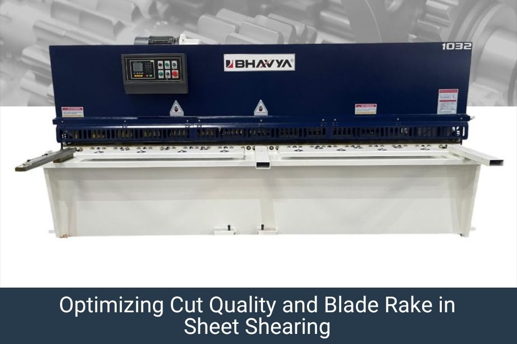
A CNC shearing machine is a sheet metal cutting machine that uses a straight, hardened blade to shear flat sheet metal into strips or blanks along a straight cutting line, controlled by a CNC backgauge system for precise repeat dimensions.
The three main types are: hydraulic swing beam shearing machine, hydraulic guillotine shearing machine, and CNC motorised shearing machine (electric drive).
CNC shearing machines are the primary blank preparation machine in sheet metal fabrication shops – feeding downstream processes like press brake bending, panel bending, and stamping.
Bhavya Machine Tools supplies hydraulic and CNC shearing machines from 1.5mm to 20mm cutting capacity, with CNC backgauge systems for precision repeat cutting across India and international markets.
Introduction: The Role of the Shearing Machine in Sheet Metal Fabrication
In any sheet metal fabrication workshop – whether making electrical enclosures, HVAC ductwork, automotive components, or construction materials – the shearing machine is the first machine in the production line. It converts large master sheets (typically 1250×2500mm or 1500×3000mm from the steel service centre) into precisely dimensioned blanks that feed every subsequent process: bending, punching, welding, and forming.
The CNC shearing machine takes this process further – adding CNC-controlled backgauge positioning for automatic, programmable, and repeatable blank dimensions. This guide explains what a CNC shearing machine is, how it works, the different types available, their applications, and how to select the right one for your operation.
A CNC (Computer Numerical Control) shearing machine is a power-driven sheet metal cutting machine in which:
A fixed lower blade (bed blade) and a moving upper blade (ram blade) are set at a small clearance angle (rake angle) to shear the sheet.
A hydraulic or electro-mechanical drive system powers the upper blade down through the material.
A CNC-controlled backgauge system positions the sheet to a precise programmed dimension before each cut.
The CNC controller stores multiple cut programs, allowing fast changeover between different blank sizes.
The result is a straight, clean, dimensionally accurate cut with no material loss (unlike laser or plasma cutting) and no heat-affected zone (unlike thermal cutting processes).
How Does a CNC Shearing Machine Work? (Working Principle)
Step 1: Sheet Loading
The operator (or an automated feeding system) places the sheet on the machine table. The sheet rests on roller ball supports or a flat bed and is pushed against the backgauge fingers, which are positioned at the programmed cut dimension.
Step 2: Sheet Clamping
The hold-down clamps (hydraulic hold-downs) descend and firmly clamp the sheet just in front of the cut line. This prevents the sheet from moving, buckling, or twisting during cutting, which would cause a crooked cut.
Step 3: Blade Descent & Shearing Action
The upper blade descends. Because the blades are set at a small rake angle (typically 0.5°-3°) rather than being perfectly horizontal, the cut progresses from one side of the sheet to the other – like scissors. This progressive cutting action dramatically reduces the required cutting force compared to a full-width simultaneous cut.
Step 4: Cut Completion & Return
As the upper blade completes its downward stroke, the sheet is sheared along the cut line. The upper blade returns to the home position, the clamps release, and the backgauge automatically moves to the next programmed position for the next cut.
Rake Angle: The Key Variable
The rake angle between the upper and lower blades determines both cut quality and required tonnage:
Blade clearance (the gap between upper and lower blade) is the most important parameter for cut quality. Correct clearance varies with material thickness:
Material Thickness (mm)
Blade Clearance (% of thickness)
Clearance (mm)
1.0
5-8%
0.05-0.08
2.0
5-7%
0.10-0.14
3.0
5-6%
0.15-0.18
6.0
5-6%
0.30-0.36
10.0
5-6%
0.50-0.60
16.0
6-8%
0.96-1.28
Too little clearance: Excessive burr, premature blade wear, high cutting force. Too much clearance: Sheet twisting, rough cut edge, poor dimensional accuracy.
Types of CNC Shearing Machines
Hydraulic Swing Beam Shearing Machine
The most common type for general sheet metal fabrication. The upper blade is mounted on a swing beam that pivots on a fixed fulcrum, creating an arc of blade movement.
Best for: Light to medium sheet thickness (0.5-6mm), general fabrication shops
Advantages: Simple, robust design; lower cost; easy blade gap adjustment
Limitations: The arc-of-cut path means a slight twist on very thick or narrow cuts
The swing beam is the workhorse of the Indian sheet metal industry and accounts for the majority of shearing machine installations.
Hydraulic Guillotine Shearing Machine
The upper blade descends vertically (or very nearly so), like a true guillotine. The blade path is a straight vertical (or very slight raked) linear motion rather than an arc.
Best for: Thicker materials (4-20mm), precision blanks where edge squareness is critical
Advantages: Straighter cut edge; better for thicker materials; ideal for structural steel blanking
Limitations: Higher cost than swing beam; more complex construction
What Our Customers Say
“Our production speed has improved ever since we got a Bhavya machine. It’s smooth, durable, and works exactly as promised.”
Instead of a hydraulic drive, this type uses a mechanical flywheel and eccentric drive, or servo-electric drives, to power the blade. Common in lighter gauge applications.
Best for: High-speed thin gauge cutting (0.5-2mm), high production environments
Advantages: Faster cycle time; lower energy consumption per cut; lower maintenance
Limitations: Generally limited to thinner materials; less torque than hydraulic types
Key Components of a CNC Shearing Machine
Component
Function
Upper Blade (Moving Blade)
Provides the cutting action; hardened tool steel; replaceable and reversible (4 cutting edges)
Hydraulic clamps that secure the sheet against vibration and movement during cutting
CNC Backgauge
CNC-positioned stop fingers that locate the sheet at the programmed cut dimension; typical accuracy ±0.1mm
Cutting Table (Bed)
Flat table with ball roller supports for smooth sheet movement; must be perfectly flat
Hydraulic Power Unit
Provides hydraulic pressure to drive the ram and hold-down clamps
CNC Controller
Programs cut dimensions, number of cuts, and cut sequence; typically E21S, ESA S530, or Delem controller
Squaring Arm
Reference edge for squaring the sheet before cutting to ensure 90° cut angle to the sheet edge
Material Support Arms
Support the cut sheet as it falls clear of the lower blade – prevents edge bending on thin material
CNC Shearing Machine Applications Across Industries
Sheet Metal Fabrication & Stamping
Shearing machines prepare flat blanks for press brake bending, power press stamping, and laser cutting. Accurate blank dimensions reduce material waste and ensure consistent part geometry in downstream operations.
Electrical Enclosure & Panel Manufacturing
CRCA and galvanised steel blanks for DB boxes, MCC panels, and cable trays are sheared to precise dimensions before bending on press brakes or panel benders.
HVAC & Ventilation Ductwork
GI and aluminium sheets are sheared into strips and blanks for duct fabrication. The CNC backgauge allows production of multiple different duct panel sizes in a single CNC program run.
Structural Steel & Construction
Flat bar, plate, and sheet steel is sheared for structural brackets, support plates, and fabricated sections. Hydraulic guillotine shearing machines are preferred here for material up to 16-20mm thickness.
Automotive Component Manufacturing
Automotive body blanks and structural reinforcements are sheared from coil-fed or sheet-fed material. High-speed CNC shearing lines with automatic feeding and stacking are used in volume automotive pressing operations.
Furniture & Home Appliance Manufacturing
Thin-gauge CRCA sheets (0.6-1.5mm) for refrigerator panels, washing machine bodies, and furniture frames are sheared on swing beam shearing machines before forming.
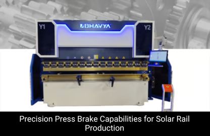
Solar Panel Frame & Renewable Energy
Aluminium and galvanised steel frame sections for solar panel mounting structures are sheared to exact lengths from coil stock, often in automated CNC shearing lines.
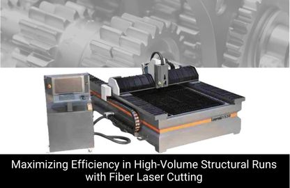
CNC Shearing Machine vs Laser Cutting: When to Use Each
Parameter
CNC Shearing Machine
Fiber Laser Cutting Machine
Cut type
Straight-line cuts only
Any 2D profile (straight, curved, complex)
Material utilisation
100% – no kerf loss
Kerf loss of 0.2-0.5mm per cut line
Cut speed
Very fast (1-3 seconds per cut)
Slower for straight cuts; faster for profiles
Cut quality (edge)
Slight burr; good for most applications
Near-zero burr; excellent edge quality
Capital cost
Low to medium (₹3-25 lac)
High (₹30-150 lac+)
Operating cost
Very low – blade wear only
Higher – laser source, gas, maintenance
Best for
High-volume straight-line blank cutting
Complex profiles, holes, notches, fine details
Material thickness range
0.5-20mm (depends on model)
0.5-25mm+ (depends on power)
How to Select the Right CNC Shearing Machine
Determine Maximum Material Thickness
This is the primary specification. Ensure the machine’s rated capacity (in mm) at the maximum material tensile strength you will cut is adequate. Most ratings are for mild steel at 400 MPa – for stainless steel (620 MPa), reduce rated capacity by ~35%.
Determine Required Working Length
Match the cutting length to your standard sheet size. Most Indian fabrication shops use 2500mm or 3000mm cutting length. For automotive or construction applications, 4000-6000mm machines are required.
CNC Backgauge Travel Range
Ensure the backgauge travel covers your minimum and maximum cut widths. Standard backgauge travel is 750mm to 1000mm. For special applications requiring very wide or very narrow strips, check travel limits carefully.
CNC backgauge accuracy is typically ±0.1mm. For precision blank cutting where downstream tooling has tight tolerances, specify ±0.05mm accuracy and verify with acceptance tests at commissioning.
Blade Material & Edge Count
High-quality machines use 6CrW2Si or equivalent high-chrome tool steel blades with 4 reversible cutting edges. This gives excellent blade life (typically 50,000-500,000 cuts between sharpening, depending on material).
CNC Shearing Machine Specifications – Bhavya Machine Tools Range
Model Type
Cutting Length
Max Thickness (Mild Steel)
CNC Controller
Backgauge Accuracy
Hydraulic Swing Beam
1500 / 2500 / 3000mm
3mm / 6mm / 8mm
E21S / Delem
±0.1mm
Hydraulic Guillotine
2500 / 3000 / 4000mm
6mm / 10mm / 16mm
E21S / ESA
±0.1mm
CNC Motorised
1250 / 2000mm
2mm / 3mm
E21S
±0.1mm
Frequently Asked Questions on CNC Shearing Machine
What is the difference between a hydraulic swing beam and a hydraulic guillotine shearing machine?
A swing beam shearing machine moves the upper blade in an arc (pivoting motion), which is simpler and lower-cost but produces a slight twist on thick or wide cuts. A guillotine shearing machine moves the upper blade in a true vertical or near-vertical linear path, producing a straighter cut edge - preferred for thicker materials (6mm+) and precision blanking applications.
How does the CNC backgauge improve shearing machine accuracy?
The CNC backgauge positions the sheet against precision stop fingers at a programmed dimension before each cut. This eliminates manual measuring and marking, achieves repeat accuracy of ±0.1mm across hundreds of cuts, and allows multi-step cutting programs (different widths in a single automatic sequence) without operator intervention.
Can a CNC shearing machine cut stainless steel?
Yes. Most hydraulic shearing machines can cut stainless steel at approximately 60-65% of their rated mild steel capacity. For example, a machine rated at 6mm mild steel can cut approximately 4mm stainless steel. Ensure proper blade clearance is set for stainless to prevent premature blade wear and rough cut edges.
How long does it take to change the blade on a CNC shearing machine?
Most modern hydraulic shearing machines have a blade quick-release system allowing blade reversal or replacement in 30-60 minutes. With 4-edge reversible blades, the blade can be turned to a fresh edge 3 times before re-sharpening is required, giving a total blade life equivalent to 4 blade changes before resharpening.
What is the lifespan of shearing machine blades?
Blade life varies considerably with material type, thickness, and quality of steel used in the blade. As a general guide: for 2mm mild steel, quality blades last 100,000-500,000 cuts per edge. For 6mm mild steel, expect 20,000-100,000 cuts per edge. Stainless steel and abrasive materials reduce blade life by 50-70%.
What CNC shearing machines does Bhavya Machine Tools supply?
Bhavya Machine Tools supplies hydraulic swing beam shearing machines, hydraulic guillotine shearing machines, and CNC motorised shearing machines in cutting lengths from 1250mm to 6000mm and capacities from 2mm to 20mm. All machines feature CNC backgauge systems with E21S, ESA, or Delem controllers. Visit https://www.bhavyamachinetools.com for full specifications, pricing, and availability.
The CNC shearing machine is the essential foundation of any sheet metal fabrication operation. Whether you are preparing blanks for bending, stamping, or laser cutting, or producing finished strips and sheets for sale – a correctly specified CNC shearing machine with an accurate backgauge system is the single most productive investment in your cutting department.
With choices ranging from light-duty swing beam machines for thin-gauge work to heavy guillotines for structural steel blanking, selecting the right machine type and specification is critical. Understanding the working principle, blade mechanics, and CNC backgauge function helps you make that selection confidently.
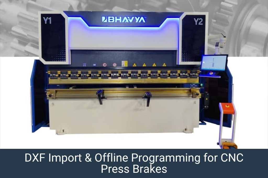
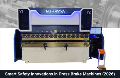
A CNC press brake is a sheet metal bending machine that utilizes computer-controlled axes, precision tooling, and backgauges to bend flat blanks into specific angles and flange dimensions.
The 7-step programming workflow includes: entering part geometry (or DXF import), tooling selection, bend sequencing, tonnage/speed calculation, backgauge setup, springback compensation, and a first-article inspection run.
Critical safety and precision rules require that the V-die opening matches material thickness (6× to 12× T), the punch tip radius prevents cracking (r ≥ T), and calculated tonnage never exceeds 80% of machine capacity.
Typical programming mistakes—such as ignoring material springback, choosing incorrect V-widths, or neglecting 3D collision simulations—result in out-of-tolerance dimensions, scrap parts, or severe machine overload.
A CNC press brake is only as productive as the operator who programs it. The machine may have a Delem DA-69T controller, servo-electric drives, and laser angle measurement – but if the bending program is incorrectly set up, the result is scrap parts, broken tooling, or in extreme cases, machine damage.
This step-by-step programming guide is written for operators with basic CNC knowledge who want to confidently program a CNC press brake for standard sheet metal bending jobs. It covers everything from reading the part drawing to running a successful first article.
What You Need Before Programming
Before you start programming, gather the following:
Part drawing or DXF file with all bend dimensions, angles, and tolerances
Material specification: grade, thickness, and yield strength (Rp0.2)
Tooling inventory: available punch tip radii, V-die openings, and lengths
Machine capability data: maximum tonnage, working length, and stroke depth
Springback compensation values for your material (from your reference table or the controller’s material database)
Most modern CNC press brakes support DXF import via USB or network. The CAM module reads the 2D flat blank development and automatically:
Identifies all bend lines and their positions
Calculates flange lengths based on the bend allowance for the material and tooling selected
Suggests a bend sequence based on collision avoidance algorithms
Always verify the imported geometry against the original drawing before proceeding. Check that bend radii and allowances match your selected tooling.
Step 2: Select Tooling (Punch & Die)
Tooling selection is one of the most important programming steps. The wrong tooling selection leads to:
Incorrect bend radius in the finished part (punch tip radius determines the inner bend radius)
Insufficient tonnage (die too narrow for material thickness)
Tooling collision with previous bends (insufficient throat depth)
V-Die Opening (V-Width) Selection Rule
The standard rule for V-die opening: V-width = 6× to 10× material thickness for mild steel; 8× to 12× for stainless steel; 6× to 8× for aluminium.
Material Thickness (mm)
Recommended V-Width (mm)
Expected Inner Radius (mm)
1.0
6-8
1.0-1.5
1.5
10-12
1.5-2.0
2.0
12-16
2.0-2.5
3.0
18-22
3.0-3.5
4.0
25-30
4.0-5.0
5.0
30-35
5.0-6.0
6.0
35-45
6.0-8.0
Punch Tip Radius Selection
The punch tip radius (r) determines the inner radius of the bent part. Select a punch tip radius equal to the specified inner bend radius in the drawing. As a minimum, the punch tip radius should not be less than the material thickness (r ≥ T) to prevent cracking.
The bend sequence is the order in which each bend is made. A correct sequence:
Prevents part-to-tooling collisions during bending
Allows all flanges to be reached by the backgauge
Minimises part handling and repositioning time
General Bend Sequence Rules
Start with internal bends (closest to the part centre) and work outward.
Make the shortest flange last if it causes collision risk.
For box shapes, make opposite bends before adjacent bends.
Use the controller’s graphical simulation to verify no collision occurs in the planned sequence.
Most modern Delem and ESA controllers have an automatic bend sequence optimiser that generates a collision-free sequence automatically. Always verify this with the 3D graphical simulation before running the part.
Step 4: Set Tonnage and Bending Speed Parameters
Tonnage Calculation
The required bending tonnage for air bending is calculated using the formula:
P = (C × T² × L × Rm) / V
Where: P = Bending force (kN), C = Constant (1.42 for air bending), T = Material thickness (mm), L = Part length being bent (mm), Rm = Ultimate tensile strength (MPa), V = V-die opening width (mm)
Most CNC controllers calculate this automatically when you enter material type, thickness, length, and die selection. Always ensure the calculated tonnage is below 80% of the machine’s maximum rated tonnage to maintain a safety margin and protect tooling.
Material
Rm (MPa)
Tonnage factor vs Mild Steel
Mild Steel (CRCA)
400
1.0×
High Strength Steel (S355)
490
1.2×
Stainless Steel 304
620
1.5×
Stainless Steel 316
580
1.4×
Aluminium 5052
230
0.6×
Copper (soft)
200
0.5×
Speed Parameters
Typical CNC press brake speed settings:
Fast approach speed (above material): 100-200 mm/s
Bending speed (during material deformation): 5-20 mm/s – slower for thicker/harder materials
“Our production speed has improved ever since we got a Bhavya machine. It’s smooth, durable, and works exactly as promised.”
Arti Mishra On Google
Step 5: Set Backgauge Position for Each Bend
The backgauge positions the sheet to achieve the correct flange length. The backgauge X-position for each bend is calculated as:
X = Flange length − (V/2) + BA/2
Where: X = Backgauge position from centreline of die, V = V-die opening, BA = Bend allowance for material and angle
The CNC controller calculates this automatically based on the entered flange length, material, and tooling. However, always verify on the first piece by measuring the actual flange length and correcting the X-offset in the program if needed.
Multi-Gauge Backgauge Setup
For parts with multiple bends, the controller stores a separate backgauge position for each bend step. During bending, the backgauge moves automatically between positions as the operator progresses through the bend sequence. Verify that the backgauge reaches each position correctly before running production.
Step 6: Set Angle Compensation (Springback Correction)
Enter the springback compensation for your material in the controller’s material setup screen. As a starting guide:
Mild steel (CRCA), 2mm thick, 90° air bend: +1°-2° overbend
Stainless steel 304, 2mm, 90° air bend: +2°-4° overbend
Aluminium 5052, 2mm, 90° air bend: +1°-3° overbend
Use the machine’s automatic angle measurement system (laser or camera-based, if equipped) to measure the actual angle after the first bend and automatically update the compensation value. This eliminates the need for manual springback tables over time.
Common CNC Press Brake Programming Mistakes & How to Avoid Them
Mistake
Consequence
Prevention
Not accounting for springback
Angle too open on finished part
Add springback compensation for each material
Wrong V-die selection for thickness
Excessive tonnage; tooling damage
Use 6-10× thickness rule for V-width
Incorrect bend allowance
Wrong flange length
Use material-specific K-factor; verify on first piece
Bend sequence causing collision
Part crashes into machine; scrap
Run 3D simulation before first piece
Tonnage exceeding 80% machine rating
Machine overload; ram deformation
Recalculate; split tooling length or select wider die
Forgetting to save the program
Re-programming required for next run
Always save with drawing number as file name
Frequently Asked Questions on CNC Press Brake Programming
What is the difference between air bending and bottoming in CNC press brake programming?
In air bending, the punch does not touch the die bottom - the sheet spans the V-die and the angle is determined by the depth of punch penetration. In bottoming (or bottom bending), the punch forces the sheet against the die bottom, and the angle is determined by the tool geometry. Air bending requires 20-30% less tonnage and allows greater flexibility of angles with fewer tools, making it the preferred method for most production bending.
How do I calculate the flat blank length for a press brake bending program?
Flat blank length = sum of all flange lengths + bend allowances for each bend. Bend allowance (BA) = (π/180) × (r + K×T) × A, where r = inner radius, K = K-factor (typically 0.33-0.5 depending on material), T = thickness, A = bend angle in degrees. Most CNC controllers calculate this automatically when you enter the bend geometry.
What CNC controller does Bhavya Machine Tools fit on its CNC press brakes?
Bhavya Machine Tools CNC press brakes are available with Delem DA-66T, DA-69T, and ESA S640 controllers - all of which support DXF import, 3D graphical simulation, and automatic springback compensation. Full programming training is provided during machine commissioning.
How long does it take to learn CNC press brake programming for basic parts?
For simple 2-4 bend parts, an operator with basic CNC familiarity can be independently programming within 2-3 days of hands-on training. Complex multi-bend parts with collision avoidance requirements typically require 1-2 weeks of practice.
Can I program a CNC press brake offline without being at the machine?
Yes. Offline programming software (such as Delem Profile-T or Lantek Expert Bend) allows you to create and simulate programs on a PC, then transfer them to the machine via USB or network. Offline programming is highly recommended for complex parts to avoid tying up the machine during programming time.
CNC press brake programming is a learnable skill that dramatically increases the productivity and quality output of your bending operation. By following this step-by-step guide – from part geometry entry through tooling selection, bend sequence, tonnage calculation, and first-article inspection – operators can consistently produce accurate, high-quality bent parts with minimal scrap.
Bhavya Machine Tools supplies CNC press brakes with Delem and ESA controllers and provides comprehensive programming training and after-sales support across India. Contact us at https://www.bhavyamachinetools.com to enquire about our CNC press brake range.
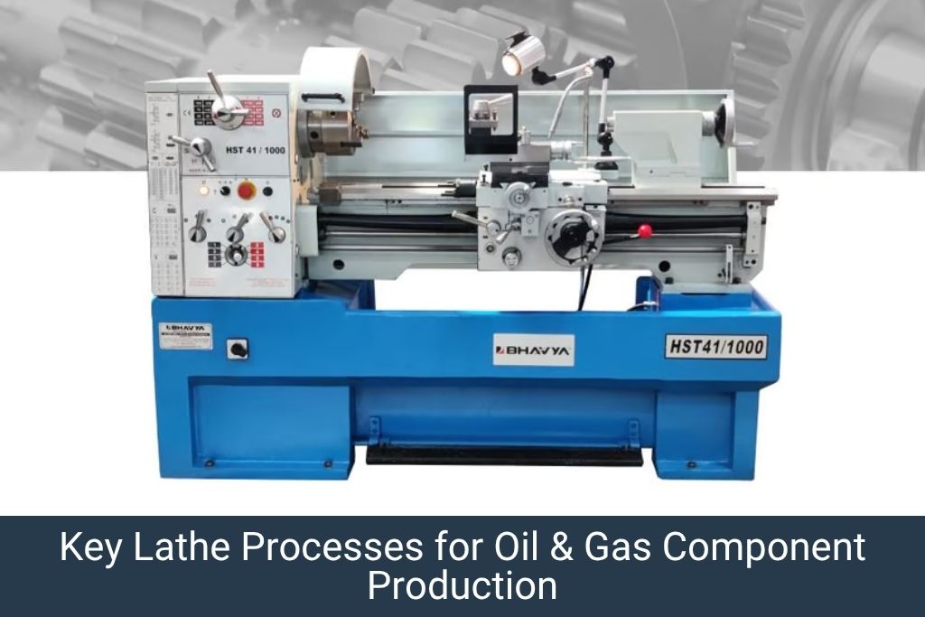
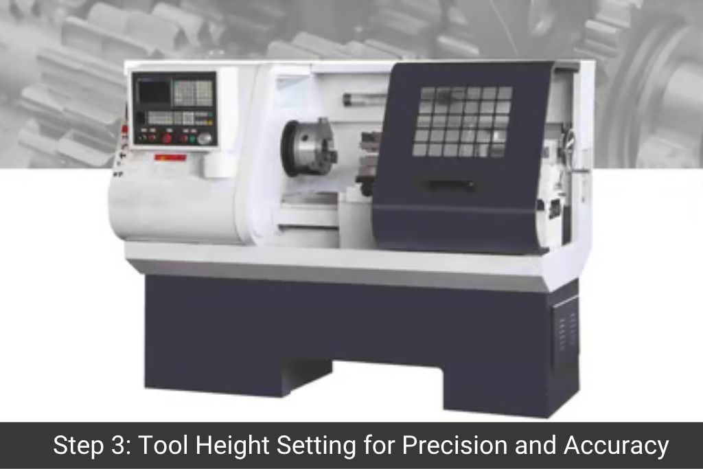
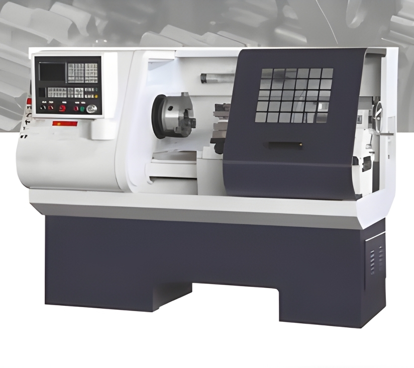
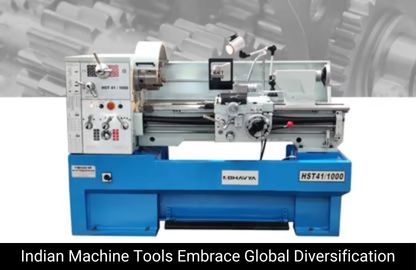
The oil and gas industry is one of the largest users of lathe machines globally, requiring precision turning operations for valve bodies, drill collars, pipe flanges, couplings, Christmas tree components, and subsea equipment.
Both conventional all-geared lathes and CNC flat bed lathes are used – conventional lathes for repair and maintenance work, CNC lathes for high-volume precision component production.
Key lathe specifications for oil & gas work include large swing-over-bed (400mm-2000mm+), long between-centres (1000mm-12,000mm), and threading capability for API, ACME, and buttress thread profiles.
Bhavya Machine Tools supplies heavy-duty, extra-heavy-duty, and CNC lathe machines suitable for oil & gas applications across India, UAE, Saudi Arabia, Oman, Kuwait, and Qatar.
Introduction: The Oil & Gas Industry’s Demand for Precision Machining
The oil and gas industry operates in the most demanding environments on earth – from desert drilling sites under extreme temperatures to offshore platforms under corrosive marine conditions. Every component in this industry must meet exacting dimensional, material, and surface finish specifications, often to API (American Petroleum Institute) standards.
The lathe machine – in both conventional and CNC configurations – is the backbone of the machining operations that produce, repair, and maintain these critical components. This article explores the specific applications, machine types, and technical requirements of lathe machines in the oil and gas sector.
Types of Lathe Machines Used in Oil & Gas Machining
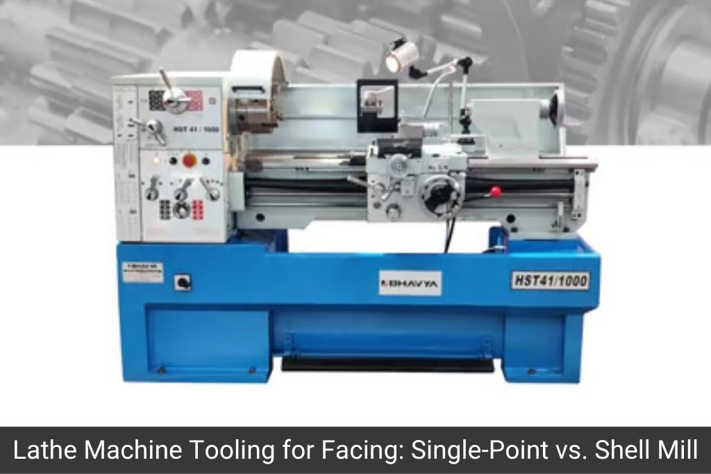
Heavy-Duty & Extra-Heavy-Duty All-Geared Lathe
For the machining of large drill collars, valve bodies, and wellhead components, heavy-duty all-geared lathes with swing-over-bed from 500mm to 2000mm and between-centres distances of 3000mm to 12,000mm are standard equipment in oil field machine shops.
The all-geared headstock provides the torque required to turn high-alloy steel components (4145H, P110, L80, C110) – materials with yield strengths of 80,000-125,000 PSI that are standard in API oil country tubular goods (OCTG).
What Our Customers Say
“Our production speed has improved ever since we got a Bhavya machine. It’s smooth, durable, and works exactly as promised.”
Arti Mishra On Google
CNC Flat Bed Lathe
CNC flat bed lathes are used for precision component production – valve internals, pump shafts, seal rings, and coupling threads – where dimensional repeatability and surface finish consistency across multiple parts are required. Modern CNC lathes with live tooling can perform threading, milling, and drilling in a single setup, reducing cycle time significantly.
Pipe Threading Lathe (Special Purpose)
Dedicated pipe threading lathes are configured for cutting API, ACME, buttress, and premium connection threads on drill pipe, tubing, and casing. These machines have specially configured threading lead screws and thread chasing dials for high-pitch oil field thread forms.
Vertical Turning Lathe (VTL)
For very large-diameter flanges, valve bodies, and wellhead spools, vertical turning lathes with tables from 1000mm to 5000mm diameter are used. The vertical axis is better suited to large, heavy workpieces that are difficult to support between horizontal centres.
Critical Lathe Operations in Oil & Gas Component Manufacturing
Drill Collar Machining – API Thread Cutting
Drill collars are the heaviest and most critical bottom-hole assembly components. They provide the weight-on-bit (WOB) for drilling and must withstand enormous torsional, tensile, and bending loads.
Lathe operations on drill collars include:
OD rough turning from forged billet to final diameter (typically 95mm-279mm OD)
ID boring of the centre bore (flow bore) to precise diameter
Box and pin API thread cutting using a threading lathe with correct lead screw pitch
API 7-2 thread inspection using ring and plug gauges after machining
The threads must meet API 7-2 dimensional tolerances to ensure proper make-up torque and leak-free connection under downhole pressure. Thread form deviations of even 0.05mm can cause connection failure in a downhole environment.
Valve Body Turning & Boring
Gate valves, ball valves, globe valves, and check valves used in wellhead, flowline, and manifold applications are precision-machined components. Lathe operations include:
OD turning of the body exterior to dimensional drawing
ID boring of valve seats and bore passages to precise diameter and finish
Flange face machining to ASME B16.5 flatness and dimension
Internal groove machining for seat rings, packing glands, and bonnet connections
The bore finish in valve components is critical – surface finish Ra 1.6 or better is required to ensure proper valve seat sealing. Hard-facing materials like Stellite, used on valve seats, must be turned with ceramic or PCBN (Polycrystalline Cubic Boron Nitride) tooling on the lathe.
ASME B16.5 and B16.47 flanges used in oil & gas piping systems require precision face machining to ensure flat, leak-free gasket contact. Lathe operations include:
Facing the flange mating face to Ra 3.2 or better (raised face) or Ra 6.3 (ring joint face)
Boring the flange bore to match pipe ID with correct finish for weld preparation
Machining the ring joint groove to RTJ dimensions (ASME B16.20)
Pump Shaft & Impeller Machining
High-pressure injection pumps, crude transfer pumps, and ESP (Electrical Submersible Pump) systems use precision-machined shafts and impellers. CNC lathe operations include:
Precision cylindrical turning of bearing journals to h6/h5 tolerance
Threading of shaft ends for impeller lock nuts
Profile turning of impeller hubs and wear rings
Concentricity of all diameters on a pump shaft must typically be within 0.02mm TIR (total indicator reading) to prevent vibration at high rotational speeds.
Frequently Asked Questions on Lathe Machines in Oil & Gas
What type of lathe is used for drilling API threads on drill collars?
Heavy-duty all-geared lathes with a large swing (typically 600mm-1000mm over bed), long distance between centres (4000mm-8000mm), and a threading capability of up to 8 TPI (API NC and regular connection threads) are used. The machine must have a rigid, backlash-free threading lead screw system to maintain API 7-2 thread accuracy.
Can a standard lathe machine handle Inconel or duplex stainless steel used in subsea components?
Yes, but with important limitations. Standard all-geared lathes can machine Inconel and duplex stainless at reduced speeds with appropriate PCBN or ceramic cutting tools. For production-volume subsea component machining, a heavy-duty CNC flat bed lathe with high-pressure coolant is recommended for cycle time efficiency and tool life.
What lathe machine specification is recommended for pipe flange facing in an oil field machine shop?
A heavy-duty all-geared lathe with swing over bed of 750mm-1000mm, 4-jaw independent chuck of 500mm-600mm, and a C-axis or facing attachment for true flat facing is recommended. For very large flanges (ASME Class 1500/2500, 24 inch+), a vertical turning lathe is more practical.
What is the minimum spindle speed required for API thread cutting on large OD drill collars?
API thread cutting on large drill collars (200mm-280mm OD) should be done at 8-15 RPM to maintain tool contact, threading lead screw synchronisation, and safe operation. Standard lathes with all-geared headstocks can achieve these low-speed, high-torque requirements.
Does Bhavya Machine Tools supply heavy-duty lathes for oil & gas applications?
Yes. Bhavya Machine Tools supplies extra-heavy-duty all-geared lathe machines with swing-over-bed up to 1600mm and between-centres distances up to 10,000mm, suitable for drill collar, valve body, and pipe flange machining. CNC flat bed lathes for oil field component production are also available. Visit https://www.bhavyamachinetools.com for full specifications.
The oil and gas industry’s demand for heavy-duty, precise, and reliable lathe machining is driven by the critical safety and performance requirements of its components. From drill collar thread cutting to valve body boring and pump shaft machining, the lathe machine remains an irreplaceable tool in every oil field machine shop.
Bhavya Machine Tools provides a comprehensive range of lathe machines – from standard all-geared lathes to heavy-duty CNC flat bed lathes – designed to meet the most demanding oil and gas machining requirements.
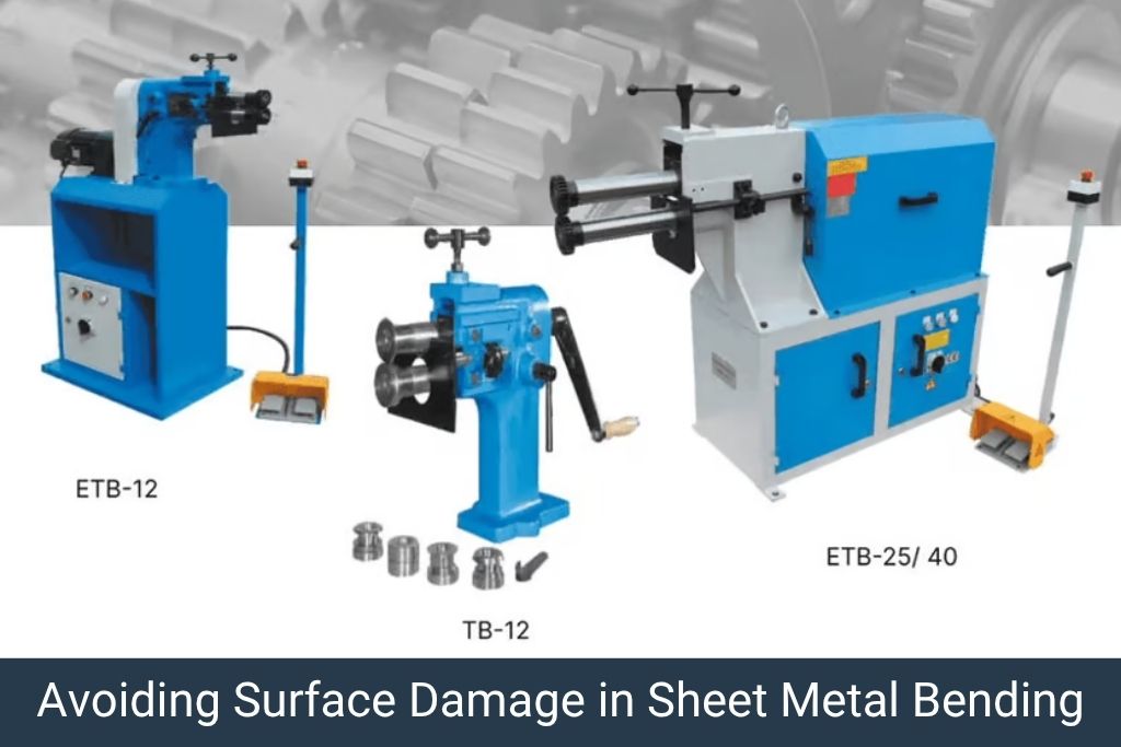
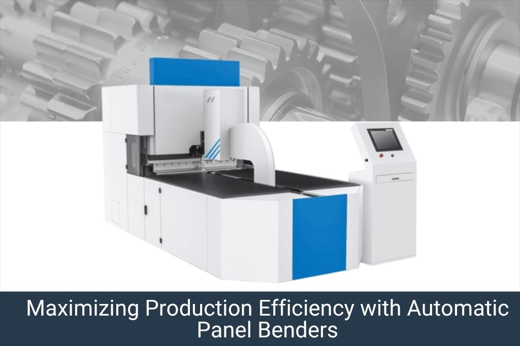
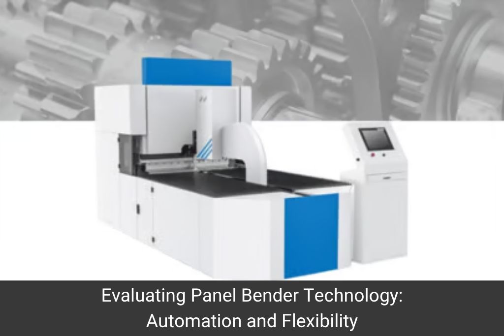
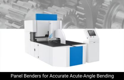
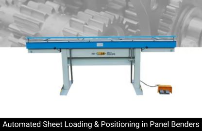
The most common errors in automatic panel bending are angular deviation, springback miscalculation, sheet surface marking, incorrect blank holder force, and dimensional errors from poor blank positioning.
Most errors are preventable through proper machine calibration, correct parameter setup, and trained operators who understand the relationship between material properties, bend angle, and springback.
CNC panel benders with automatic angle measurement and springback compensation features can self-correct most of these errors in real-time during production.
Bhavya Machine Tools provides operator training and technical support for all panel benders supplied, ensuring customers achieve consistent quality from day one.
Introduction: Why Panel Bending Errors Are Costly
An automatic panel bender is a high-precision CNC machine, but like any manufacturing equipment, it can produce errors when not set up correctly, when material properties vary, or when the machine’s mechanical systems drift out of calibration. Understanding these errors – what causes them and how to prevent them – is essential for any sheet metal fabrication business relying on panel bending for production.
In electrical enclosure manufacturing, HVAC ductwork, elevator panelling, and architectural cladding – where tight tolerances and surface quality are non-negotiable – panel bending errors translate directly into rework costs, material wastage, and delayed deliveries. This guide covers the 10 most common automatic panel bending errors, their root causes, and concrete corrective actions.
Error 1: Angular Deviation – Incorrect Bend Angle
Symptoms
The bent angle measured on the finished part does not match the programmed angle. Deviations of 1°-3° are common when setup parameters are not optimised for the specific material batch.
Root Causes
Springback not accounted for in the CNC program – the most common cause
Material yield strength variation between batches (even same grade/thickness can vary ±15%)
Worn or incorrect bending blade geometry
Blade clearance set incorrectly for the sheet thickness
How to Avoid It
Always run a test bend on a sample piece from the actual production batch before starting production.
Use the machine’s automatic angle correction feature (available on most modern CNC panel benders).
Create and maintain a springback compensation table for each material grade and thickness.
Inspect bending blades regularly and replace if radius wear is detectable.
After bending, the sheet springs back partially, resulting in an angle larger (more open) than intended. This is especially pronounced with high-tensile steel, stainless steel, and aluminium alloys.
Root Causes
Elastic recovery is an inherent property of all metals – the higher the yield strength, the greater the springback.
Insufficient overbend angle in the CNC program.
Using inappropriate blade geometry for the material.
How to Avoid It
Calculate the springback compensation angle for each material type and add it to the CNC bend angle program. Stainless steel typically requires 2°-4° overbend; aluminium 1°-3°; CRCA mild steel 0.5°-2°.
Use adaptive bending mode (available on advanced CNC panel benders) that measures the actual angle mid-bend and compensates automatically.
Consult material data sheets for yield strength (Rp0.2) – this is the key predictor of springback magnitude.
The flange length (distance from bend line to sheet edge) is shorter or longer than specified. Deviations greater than ±0.5mm cause assembly problems in enclosure manufacturing.
Root Causes
Incorrect blank size (cutting error from upstream process).
Sheet not positioned correctly against the backgauge stop.
Backgauge stop wear or loose stop fingers.
Thermal expansion of the machine bed during extended production runs.
How to Avoid It
Verify blank dimensions before loading – use a measuring tape or CMM for critical parts.
Error 7: Blade Collision with Pre-Punched Features
Symptoms
Bending blade strikes a punched hole, slot, or notch in the sheet, causing blade damage and/or deformation of the sheet near the feature.
Root Causes
CNC program not accounting for hole/slot positions relative to the bend line.
Incorrect blank feeding orientation (sheet loaded backwards or mirrored).
DXF import error where hole data is not correctly associated with the part geometry.
How to Avoid It
Always verify the CNC program with a graphical simulation before running the first piece.
Check that DXF import correctly identifies all internal features (holes, slots, notches).
Mark a reference corner on the blank and verify orientation matches the CNC program orientation before each production run.
Use minimum flange width limits defined in the machine’s tooling capability chart to ensure no blade overlap with punched features.
What Our Customers Say
“Largest Display of Machinery across India. Wide range of Machines. Very Co-operative staff. Range of Tapping Machine and Re-sharpening Machines are outstanding. Very Cost effective and useful in Precision Machining Work. Their staff is co – operative for after sales support.”
Tirth Bhojani On Google
Error 8: Blank Holder Damage from Over-Clamping
Symptoms
Deformation of the sheet at the clamped area – a raised ridge or compression mark at the backgauge edge of the part.
Root Causes
Blank holder force set too high for the sheet thickness.
Using wrong blank holder insert type for soft materials (e.g., standard steel insert used on aluminium).
How to Avoid It
Refer to the machine manufacturer’s clamping force table for each material and thickness combination.
Use material-appropriate blank holder inserts – polyurethane-faced inserts for aluminium and coated sheets.
Reduce clamping force incrementally until the sheet holds without slipping but shows no surface marking.
Parts that were previously acceptable start showing systematic angular or dimensional errors across all production, even with correct programming.
Root Causes
Wear in the bending blade drive system (lead screw, servo coupling).
Blade reference position drifting due to encoder battery failure or motor coupling slip.
Machine bed or column deformation from impact or long-term thermal cycling.
How to Avoid It
Schedule a full machine geometric calibration every 6 months.
Check and replace servo encoder batteries annually.
Inspect blade drive lead screws and couplings for wear every 6 months.
After any machine collision or hard crash, perform a full geometric re-calibration before returning to production.
Panel Bending Error Diagnostic Quick Reference
Symptom
Most Likely Cause
Quick Fix
Angle too open (>target)
Springback undercompensated
Increase overbend angle in program
Angle too closed (<target)
Overbend too aggressive
Reduce overbend angle; check blade wear
Surface scratch on face
Clamping force too high or dirty blank holder
Reduce force; clean clamping surface
Twist in long panels
Coil stress or uneven clamping
Pre-level sheet; check blank holder parallelism
Flange length wrong
Backgauge stop worn or blank wrong size
Re-measure blank; replace stop inserts
Blade hits punched feature
Program not accounting for holes
Re-simulate; verify blank orientation
Inconsistent batch quality
Thermal drift or material variation
In-process checks every 50 parts
Frequently Asked Questions on Automatic Panel Bending Errors
What is the most common cause of angular errors on a CNC panel bender?
Springback is the most common cause. Every metal sheet springs back elastically after bending. If the springback angle is not pre-programmed as an overbend compensation, the finished angle will be larger (more open) than specified. The exact springback depends on material grade, yield strength, thickness, and bend radius.
How can I prevent scratches on stainless steel sheets during panel bending?
Use stainless-specific blade inserts with high-quality polished surfaces, reduce blank holder clamping force to the minimum required, clean the blank holder and blade surfaces before each run, and apply a thin protective PVC film on the sheet if surface finish is critical.
Why do my panel bending dimensions drift over a long production run?
Thermal expansion of the machine structure and tooling causes dimensional creep over extended production. Allow the machine to reach thermal equilibrium before precision production, use the in-process angle correction feature, and schedule dimensional checks every 50-100 parts.
Can I prevent blade collision with pre-punched holes automatically?
Modern CNC panel benders with feature-aware CAM software will automatically detect hole and slot positions from the DXF import and alert the operator if a blade collision risk exists. Always run the graphical simulation and verify the program before running the first physical part.
How often should a CNC panel bender be recalibrated for production accuracy?
A full geometric calibration should be performed every 6 months or after any hard crash/collision. Regular 6-monthly calibration keeps angular accuracy within ±0.2° and flange dimensional accuracy within ±0.3mm.
Automatic panel bending errors are not inevitable – they are preventable. With proper machine setup, trained operators, regular maintenance, and in-process quality checks, modern CNC panel benders consistently deliver angular accuracy within ±0.2° and dimensional tolerances within ±0.3mm.
Bhavya Machine Tools provides comprehensive operator training, maintenance guidance, and after-sales support for all automatic panel benders. Visit https://www.bhavyamachinetools.com to learn more about our panel bender range and support services.
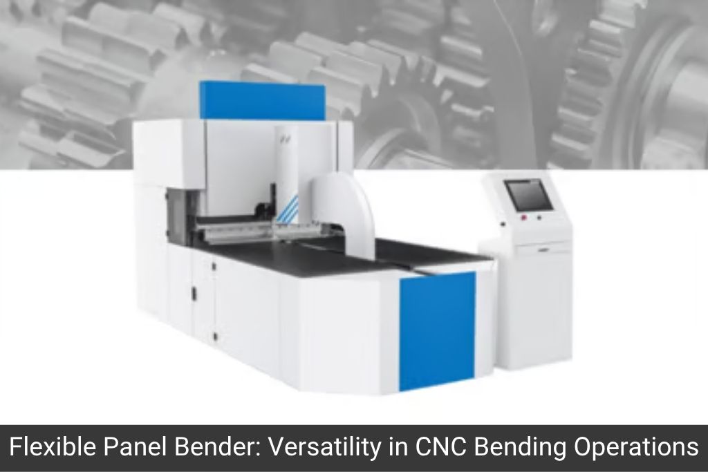
Automatic panel benders are the preferred bending solution for electrical enclosure and switchgear manufacturers because they deliver consistent, scratch-free bends with tight angular tolerances on pre-punched sheets.
Key advantages over press brakes include: single-operator operation, no manual repositioning, automatic tool change, and the ability to make sequential complex bends (boxes, channels, U-profiles) without scratch or deformation.
Electrical enclosure manufacturers in India, UAE, and GCC markets are switching to CNC automatic panel benders to meet IEC/ISO dimensional tolerances and reduce rework rates below 0.5%.
Bhavya Machine Tools supplies automatic panel benders suitable for producing MCC panels, DB boxes, cable trays, bus duct housings, and LT/HT switchgear enclosures.
Introduction: The Electrical Enclosure Manufacturing Challenge
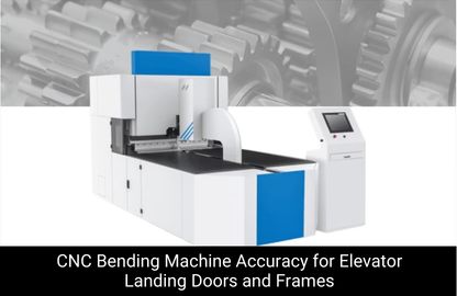
Electrical enclosures – from distribution board (DB) boxes and motor control centres (MCCs) to high-voltage switchgear cabinets – must meet precise dimensional tolerances, clean internal surfaces, and consistent angular geometry to ensure safe assembly, IP-rated sealing, and compliance with IEC 61439, IEC 62208, and IS 13947 standards.
Traditional press brake bending, while versatile, poses critical challenges in this application: each bend requires manual part repositioning, increasing the risk of scratches on pre-painted or pre-coated sheets, angular inconsistencies between bends, and high operator skill dependency.
The automatic CNC panel bender eliminates all of these issues. This article explains how automatic panel benders work in the context of electrical enclosure manufacturing, what productivity and quality gains they deliver, and how to select the right machine for your production needs.
An automatic panel bender is a CNC sheet metal bending machine where the bending tool (blade) moves around the sheet – rather than the sheet being repositioned for each bend. The sheet is held by a blank holder, and the upper and lower bending blades execute positive and negative bends in sequence, automatically, under CNC control.
This fundamentally different bending mechanism means:
The sheet surface never contacts a press brake punch or die during bending – eliminating scratches.
All bends on a component are executed in a single setup – no manual repositioning.
Complex profiles (box shapes, U-channels, Z-profiles, multiple flanges) are completed in seconds.
A single operator can run the machine – loading flat blanks and unloading finished components.
Scratch-Free Bending on Pre-Painted & Pre-Coated Sheets
Electrical enclosure manufacturers frequently work with pre-painted CRCA steel, pre-galvanised sheets, and powder-coated blanks. Press brake tooling inevitably leaves witness marks or scratches on coated surfaces, requiring expensive touch-up painting.
The automatic panel bender’s blank holder grips the sheet on the clamping edge, and the bending blades never contact the sheet face. This is critical for IP54/IP65 enclosure manufacturers who cannot afford to compromise surface finish.
Consistent Angular Accuracy Across All Bends
IEC 61439 compliant switchgear enclosures require angular tolerances typically within ±0.5°. On a press brake, maintaining this across 8-12 bends per enclosure side requires an experienced operator and frequent re-checks. On an automatic panel bender, the CNC system controls every bend angle independently, consistently achieving ±0.2° across all bends.
High Throughput for Medium to High Volume Production
A standard 19-inch rack enclosure front panel with 6 bends takes approximately 4-6 minutes on a press brake (including repositioning). The same part runs in under 90 seconds on an automatic panel bender. For a production volume of 200 enclosures per day, this translates to 10+ additional productive hours per shift.
Ability to Bend Pre-Punched & Pre-Drilled Sheets
Electrical enclosures typically have punched holes, cable entry knockouts, and mounting slots before bending. Press brakes require careful operator skill to avoid bending errors around these features. The automatic panel bender’s CNC system accounts for these features automatically, maintaining dimensional accuracy regardless of hole patterns.
Single-Operator Productivity
Panel benders require only one operator to load, monitor, and unload parts. This is a significant labour cost advantage compared to press brake operations that typically require two operators for larger enclosure panels (one to hold, one to operate the foot pedal).
Frequently Asked Questions on Automatic Panel Bender for Electrical Enclosures
Can an automatic panel bender handle galvanised steel sheets for electrical enclosures?
Yes. Automatic panel benders are specifically suited to galvanised and pre-coated sheets because they do not scratch the zinc or coating layer during bending. The blank holder force is adjustable to prevent marking on delicate surfaces.
What is the minimum flange height achievable on a panel bender for enclosure work?
Most automatic panel benders can achieve minimum flange heights of 6-10mm depending on the blade configuration and sheet thickness. For DB box and cable tray manufacturing, standard flanges of 15-25mm are easily achievable.
How quickly can a new operator learn to program a CNC panel bender for enclosure production?
With a modern CNC panel bender featuring graphical programming and DXF import, a new operator with basic CNC experience can be producing parts independently within 1-2 weeks of training.
Can the panel bender make the internal flanges and return lips required on enclosures?
Yes. This is one of the key advantages of panel benders. The positive and negative bending blades can produce inward (return) flanges and complex multi-directional profiles that would be very difficult to produce on a press brake without custom tooling.
Which panel bender model does Bhavya Machine Tools recommend for electrical enclosure manufacturing?
Bhavya Machine Tools offers automatic panel benders in 2000mm, 2500mm, and 3000mm working lengths, with sheet capacity up to 3mm CRCA. For electrical enclosure work, the 2500mm model with segmented tooling is most popular. Contact us at https://www.bhavyamachinetools.com for a detailed specification sheet and production video.
For electrical enclosure and switchgear manufacturers, the automatic CNC panel bender is not simply an upgrade to the press brake – it is a fundamentally different and superior manufacturing process. The combination of scratch-free operation, single-setup multi-bend capability, high throughput, and CNC-precision makes it the machine of choice for DB box, MCC panel, switchgear cabinet, and cable tray production.
Contact Bhavya Machine Tools to explore automatic panel bender options for your enclosure manufacturing requirements.
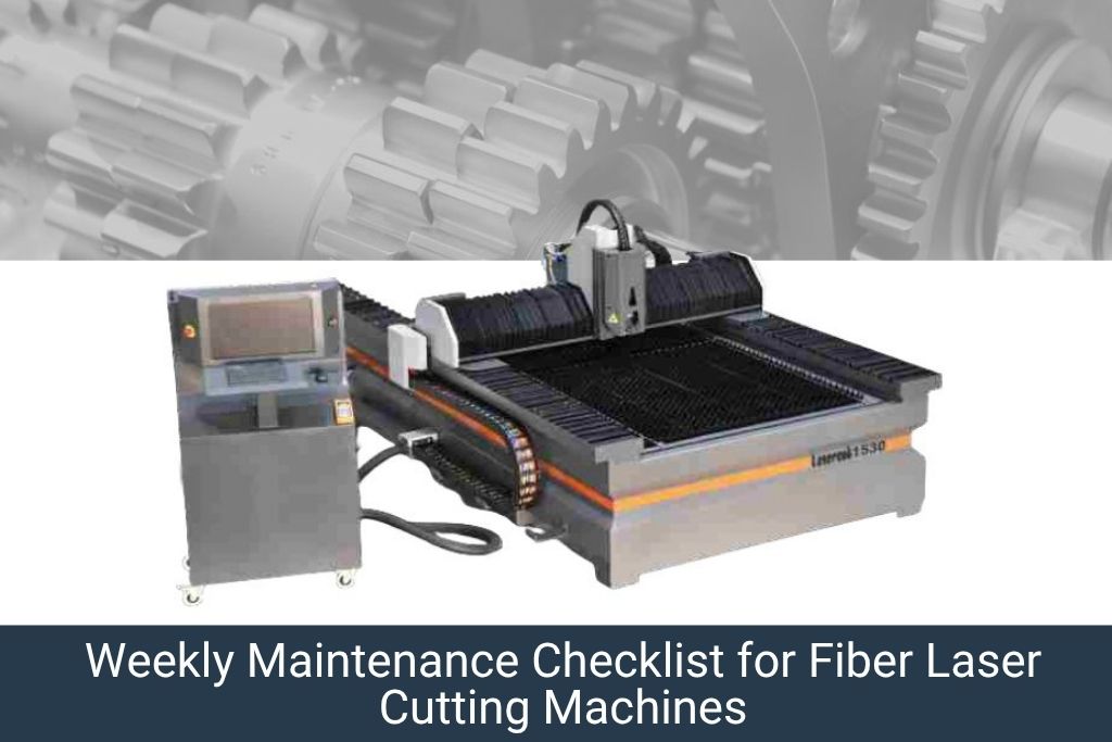
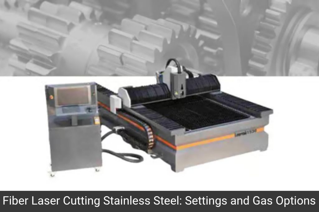
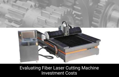
A fiber laser cutting machine requires structured preventive maintenance across daily, weekly, monthly, and annual intervals to ensure peak performance and longevity.
Key maintenance areas include: cleaning the cutting head & lens, checking assist gas pressure, inspecting the chiller water temperature, lubricating linear rails, and regularly calibrating the focus position.
Neglecting maintenance can result in poor cut quality, increased kerf width, burnt edges, beam misalignment, and expensive component replacements.
Bhavya Machine Tools (www.bhavyamachinetools.com) offers after-sales service, genuine spare parts, and AMC contracts for all fiber laser cutting machines supplied across India and GCC markets.
A fiber laser cutting machine is one of the highest-value capital investments in any sheet metal fabrication workshop. Whether you are cutting mild steel, stainless steel, aluminium, copper, or brass – the machine’s precision, speed, and edge quality depend directly on the quality of its maintenance.
In India’s competitive manufacturing landscape, unplanned downtime of even a single shift can result in lost orders, delayed deliveries, and avoidable repair costs running into lakhs of rupees. A well-documented preventive maintenance plan eliminates most of these risks.
This guide from Bhavya Machine Tools gives you a complete, actionable fiber laser cutting machine maintenance checklist – structured by daily, weekly, monthly, and annual tasks – along with the best practices followed by leading fabrication shops across India, UAE, Saudi Arabia, and East Africa.
How a Fiber Laser Cutting Machine Works: Quick Technical Overview
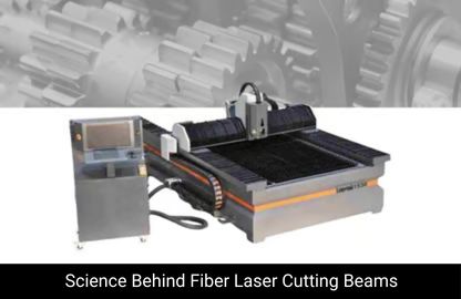
Understanding what you are maintaining helps you maintain it better. A fiber laser cutting machine generates a high-powered laser beam through a fiber optic cable from a laser source (typically IPG, Raycus, MAX, or JPT). The beam is focused through a cutting head onto the workpiece. Assist gases (nitrogen, oxygen, or air) blow the molten metal away to create a clean cut.
The key sub-systems requiring maintenance are:
Laser source (fiber module)
Cutting head (lens, nozzle, ceramic ring)
Chiller / water cooling unit
Linear motion system (rails, rack & pinion, servo drives)
Best Practices for Fiber Laser Cutting Machine Longevity
Use Only Genuine Spare Parts
Always use OEM-recommended lenses, nozzles, and ceramic rings. Third-party low-quality optical components are the single biggest cause of premature laser source damage.
Maintain a Maintenance Log
Record every maintenance activity with date, technician name, parts replaced, and observations. This log is invaluable for warranty claims and for diagnosing recurring problems.
Train Your Operators
Most maintenance issues originate from operator errors: wrong gas selection, excessive pierce time on thick materials, or incorrect focus settings. Regular operator training pays dividends immediately.
Control the Operating Environment
Fiber laser cutting machines perform best in a dust-reduced, temperature-stable environment. Ambient temperature should ideally stay between 15°C and 30°C. High humidity accelerates corrosion of the beam delivery optics.
Never Skip the Warm-Up Cycle
Always run the machine warm-up cycle (typically 3-5 minutes) before beginning production cutting, especially in the morning or after extended shutdown. This allows the chiller to stabilize and the servo systems to reach operating temperature.
Frequently Asked Questions on Fiber Laser Cutting Machine Maintenance
How often should I clean the protective lens on a fiber laser cutting machine?
The protective lens should be inspected every day and cleaned as needed. In heavy-duty cutting environments (especially with mild steel and oxygen assist gas), it may need cleaning 2-3 times per shift. A contaminated lens is the most common cause of sudden power loss and poor cut quality.
What type of water should be used in the fiber laser chiller?
Always use distilled or deionized water in the chiller circuit. Tap water contains minerals that deposit scale inside the coolant circuit and on the laser source cooling passages, restricting flow and causing thermal damage over time.
How do I know if my fiber laser focus position needs recalibration?
Signs of focus drift include: increased dross on the cut bottom, wider kerf than expected, rough cut surface, or burn marks at pierce points. Run the auto-focus calibration from the CNC panel, or do a manual focus test by cutting a series of lines at different Z-offsets and identifying the sharpest result.
How long does a fiber laser source last with proper maintenance?
A well-maintained fiber laser source from reputable manufacturers typically lasts 100,000 hours or more. Without proper maintenance - especially chiller maintenance and lens cleanliness - this can drop to 20,000-50,000 hours.
What is the best way to clean a fiber laser cutting machine lens?
Use optical-grade lens tissue with 99% isopropyl alcohol or dedicated optical cleaning solution. Never use compressed air directly on the lens surface. Wipe in a single direction - never circular motions - to avoid scratching the anti-reflection coating.
Does Bhavya Machine Tools offer Annual Maintenance Contracts (AMC) for fiber laser cutting machines?
Yes. Bhavya Machine Tools provides AMC and after-sales service support for all fiber laser cutting machines supplied by us. Contact us at https://www.bhavyamachinetools.com for AMC pricing, spare parts supply, and on-site service scheduling across India and the GCC region.
A fiber laser cutting machine is a precision instrument that rewards disciplined maintenance with years of high-quality, profitable operation. By following this preventive maintenance checklist – daily, weekly, monthly, and annually – you protect your capital investment, minimize downtime, and deliver consistently superior cut quality to your customers.
Pune Machine Tool Expo 2026 represents Western India’s premier platform for precision engineering, advanced manufacturing technology, and industrial machinery innovation. Taking place September 7-10, 2026, at Pune International Exhibition and Convention Center in Moshi, Pune, this distinguished event connects leading machine tool manufacturers, automation specialists, industrial equipment providers, and manufacturing professionals. Pune’s established position as an automotive and engineering manufacturing hub, combined with its presence as India’s fourth-largest manufacturing center, makes this exhibition an essential venue for industrial professionals across Maharashtra, Karnataka, Goa, and beyond. Bhavya Machine Tools participates actively, presenting comprehensive precision engineering solutions designed to help Pune’s renowned manufacturing community achieve excellence, innovation, and sustainable growth in domestic and international markets.
Introduction
Pune holds a special place in India’s manufacturing landscape. Often referred to as the “Detroit of India,” Pune is home to some of the country’s most advanced automotive manufacturers, engineering companies, and precision equipment specialists. From automotive OEMs to international automotive suppliers, from aerospace component manufacturers to general precision engineering firms, Pune’s manufacturing ecosystem represents the forefront of India’s industrial capability and innovation. As this established manufacturing center continues to evolve and modernize, the need for cutting-edge machinery, advanced automation solutions, and precision equipment becomes increasingly critical for competitive sustainability. Pune Machine Tool Expo 2026 emerges as the quintessential platform where Pune’s manufacturing leadership converges with equipment innovators, technology providers, and industrial entrepreneurs to explore manufacturing excellence, evaluate equipment investments, and strengthen the industrial ecosystem.
Scheduled for September 7-10, 2026 at the prestigious Pune International Exhibition and Convention Center in Moshi, Pune, this exhibition promises to showcase the breadth and sophistication of India’s manufacturing technology landscape. With hundreds of exhibitors ranging from established machine tool manufacturers to cutting-edge automation specialists, the expo provides a comprehensive platform for manufacturing professionals, factory owners, procurement teams, engineers, and business leaders to discover solutions that can accelerate their manufacturing transformation.
Bhavya Machine Tools, with 30+ years of dedicated experience serving Pune’s manufacturing community and India’s industrial sector, will showcase its comprehensive range of precision engineering solutions at Stall No. C113. Whether you’re evaluating equipment for automotive manufacturing, exploring advanced CNC systems for precision components, identifying automation solutions for productivity enhancement, or seeking long-term partnerships with proven equipment suppliers, Pune Machine Tool Expo 2026 offers the ideal opportunity to connect with technical expertise and tested manufacturing solutions.
What is Pune Machine Tool Expo?
Pune Machine Tool Expo is India’s premier showcase dedicated to machine tools, precision equipment, manufacturing automation, and industrial machinery. As a comprehensive platform for manufacturing technology and innovation, this expo brings together:
Exporters & International Traders: Companies serving international markets seeking global standard equipment
Technology Integration Partners: System integrators and technology implementation specialists
The Pune Machine Tool Expo is distinctly positioned as a sophisticated, technology-focused exhibition serving serious manufacturing professionals and industrial decision-makers.
Evaluate latest manufacturing technologies and capabilities
Understand where automotive manufacturing technology is heading
Connect with innovation leaders in manufacturing equipment
Plan equipment strategies supporting longterm competitiveness
What Our Customers Say
“Largest Display of Machinery across India. Wide range of Machines. Very Co-operative staff. Range of Tapping Machine and Re-sharpening Machines are outstanding. Very Cost effective and useful in Precision Machining Work. Their staff is co – operative for after sales support.”
Tirth Bhojani On Google
For Aerospace Component Manufacturers
Uncompromising Precision: Aerospace demands exceptional quality and precision:
Bhavya Machine Tools brings 30+ years of proven expertise serving Pune’s renowned manufacturing community. We understand Pune’s industries, challenges, competitive landscape, and excellence standards. This deep understanding informs how we serve customers.
Our Commitment to Pune’s Manufacturing Excellence
Three Decades of Pune Partnership: Our long presence in Pune reflects deep commitment to the region’s manufacturing leadership and success.
Industry Insights: Gain perspective on market trends and directions
Exhibition-Period Value Adds
Many exhibitors offer special benefits for exhibition attendees:
Exclusive Pricing: Special rates for exhibition visitors only
Flexible Financing: Customized payment terms for exhibition purchases
Complimentary Services: Free training, installation, or service packages
Extended Warranties: Special guarantee terms
Why Choose Bhavya Machine Tools
Three Decades Serving Pune’s Manufacturing Community
30+ years of partnership with Pune’s automotive, aerospace, and precision manufacturing sectors demonstrates deep understanding and proven reliability.
Comprehensive Equipment Portfolio
From conventional machines to advanced CNC systems, from hydraulic equipment to specialized solutions—comprehensive options for diverse needs.
Advanced Technology Integration
While maintaining proven fundamentals, we continuously integrate latest innovations enabling competitive advantage.
Customization & Engineering Excellence
Rather than standard configurations, purpose-engineered solutions matched perfectly to your requirements.
ISO 9001:2015 Certification
Quality management systems certification ensuring consistent excellence across manufacturing, service, and support.
Strong Pune Presence
Service infrastructure and technical support across Pune ensuring responsive, efficient customer support.
Industry-Specific Expertise
Deep understanding of different manufacturing sectors enabling contextual, sector-specific recommendations.
Uncompromising After-Sales Support
Comprehensive support because equipment purchase begins, not ends, our customer relationship.
Flexible Financing & Leasing Options
Understanding equipment investment significance, we partner with financial institutions offering flexible terms.
International Standards Compliance
Equipment meeting global standards enabling businesses to serve international markets and meet export requirements.
Visit Bhavya Machine Tools at Pune Machine Tool Expo 2026 (September 7-10, 2026) at Stall No. C113, Pune International Exhibition and Convention Center, Moshi, Pune.
Plan Your Exhibition Visit:
Consult with Our Manufacturing Experts about your production requirements, challenges, and equipment needs.
Experience Live Equipment Demonstrations showcasing advanced CNC systems, automation solutions, and precision machinery in operation.
Explore Customization Capabilities tailored specifically to your manufacturing requirements and specifications.
Take Advantage of Expo Special Offers including exclusive pricing, flexible financing, and premium service packages.
Schedule Your Technical Consultation with specialists evaluating how advanced equipment can enhance your operations.
Pune Regional Support: Strong local presence and service infrastructure
Bring your manufacturing requirements and specific challenges. Our experienced team is prepared to deliver tailored solutions backed by 30 years of excellence serving Pune’s manufacturing community.
What equipment will Bhavya showcase at Pune Machine Tool Expo 2026?
We showcase comprehensive solutions including advanced CNC machining centers, precision lathes, automotive and aerospace-grade equipment, hydraulic systems, sheet metal machinery, and specialized manufacturing solutions. Live demonstrations will highlight precision capabilities, productivity improvements, and customization options.
How does Bhavya support automotive manufacturers specifically?
With extensive experience in Pune's automotive sector, we supply equipment meeting ISO/TS 16949 standards, understand automotive supply chain requirements, support rapid product changeovers, and provide solutions enabling just-in-time manufacturing. Our team understands automotive sector challenges and requirements intimately.
Can equipment be customized for unique manufacturing applications?
Absolutely. Customization is a core competency. Our engineering team designs equipment specifically for your manufacturing requirements—whether unique component geometry, specialized production volumes, or industry-specific standards. We deliver purpose-engineered solutions, not standard machines.
What after-sales support does Bhavya provide to Pune customers?
Comprehensive support including expert installation, operator and maintenance training, preventive maintenance programs, 24/7 technical support, genuine spare parts supply, and ongoing performance optimization. Our strong Pune presence ensures responsive, efficient support.
Does Bhavya supply aerospace-grade equipment meeting AS9100 standards?
Yes, we supply equipment meeting AS9100 (aerospace), ISO/TS 16949 (automotive), and other international standards. Our team ensures equipment specifications and certifications meet your industry requirements.
What is typical ROI for machinery investment in manufacturing?
ROI depends on your specific application and current operations. Our team calculates realistic ROI for your scenario, typically ranging from 2-4 years for properly selected equipment in appropriate applications.
Are financing and leasing options available?
Yes, we partner with financial institutions offering flexible financing and leasing options. Our team can discuss different payment plans suited to your investment capabilities.
How can I prepare for a visit to your stall at the expo?
Prepare by identifying your key manufacturing challenges, production volumes, precision requirements, and budget parameters. Bring this information to our stall to receive detailed, tailored recommendations from our technical team.
Does Bhavya support equipment integration into existing production?
Yes, integration is a core competency. We work with your existing operations to integrate new equipment seamlessly, modify workflows as needed, and optimize your complete production system.
Are refurbished or used equipment options available?
Yes, we offer quality refurbished and used machinery at significantly lower cost. All refurbished machines undergo comprehensive testing and include warranties, providing cost-effective solutions for budget-conscious buyers.
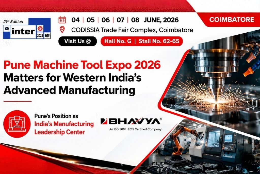
INTER Expo 2026 in Coimbatore represents one of India’s most significant platforms for engineering and infrastructure advancement, bringing together machine tool manufacturers, industrial buyers, engineers, and procurement professionals. Held June 4-8, 2026, at CODISSIA Trade Fair Complex, this exhibition showcases the latest innovations in precision engineering, CNC technology, automation solutions, and manufacturing advancements. Bhavya Machine Tools participates with comprehensive industrial machinery solutions designed to help manufacturers enhance productivity, achieve precision, and optimize production efficiency. The exhibition provides a unique opportunity for domestic and international buyers, factory owners, and engineering teams to explore next-generation manufacturing technologies and connect with industry-leading equipment suppliers.
Introduction
The manufacturing landscape in India is undergoing a significant transformation driven by automation, precision engineering, and technological innovation. As industries across automotive, aerospace, fabrication, and metalworking sectors strive for greater efficiency and quality, the need for advanced machine tools and manufacturing solutions has never been more critical. INTER Expo 2026 in Coimbatore emerges as the ideal platform where industrial innovators, machine tool manufacturers, and end-user industries converge to explore the future of precision engineering and manufacturing excellence.
Hosted at the prestigious CODISSIA Trade Fair Complex from June 4-8, 2026, INTER Expo 2026 is specifically designed to cater to the engineering and infrastructure sectors. This 21st edition promises to be a landmark event, featuring hundreds of exhibitors displaying cutting-edge CNC machines, hydraulic equipment, drilling machines, milling machines, sheet metal machinery, and specialized industrial solutions. For manufacturing professionals, procurement teams, and industrial entrepreneurs, this exhibition represents an unmissable opportunity to stay ahead of technological advancements and make informed investment decisions.
Bhavya Machine Tools, with over three decades of industry expertise, will be showcasing its comprehensive range of precision-engineered machine tools and industrial solutions at Hall No. G, Stall No. 62-65. Whether you’re a factory owner seeking to upgrade your production capabilities, an engineer exploring advanced manufacturing technologies, or a procurement manager evaluating the latest industrial equipment, INTER Expo 2026 offers the perfect venue to discover solutions that can transform your manufacturing operations.
What is INTER Expo 2026?
INTER Expo is India’s premier exhibition dedicated to the engineering, infrastructure, and manufacturing sectors. As a specialized platform for precision engineering and industrial machinery, INTER Expo 2026 brings together:
Machine Tool Manufacturers: Leading suppliers of CNC machines, lathes, drilling machines, milling machines, and specialized equipment
Industrial Equipment Providers: Hydraulic systems, sheet metal machinery, gear cutting equipment, and workshop solutions
Technology Innovators: Automation specialists, Industry 4.0 solution providers, and digital manufacturing experts
Industrial Buyers: Factory owners, production managers, procurement teams, and engineering professionals
ExportOriented Manufacturers: Companies seeking international equipment partnerships and global sourcing opportunities
This exhibition is meticulously structured to facilitate meaningful business interactions, product demonstrations, and technical discussions that directly impact industrial decision-making.
India’s manufacturing sector is at a critical juncture. With the government’s ambitious “Make in India” initiative and the emphasis on self-reliance (Atmanirbhar Bharat), manufacturing units across the country are seeking ways to enhance competitiveness, improve product quality, and increase production capacity. INTER Expo 2026 directly supports this vision by:
Showcasing Advanced Manufacturing Technologies: The exhibition features the latest innovations in CNC machining, precision engineering, and automated manufacturing solutions that enable Indian manufacturers to compete globally.
Facilitating Technology Adoption: Many Indian SMEs and mid-sized manufacturers still operate with conventional machinery. INTER Expo provides a platform to understand modern alternatives and explore automation options that improve efficiency and reduce labor dependency.
Connecting Supply Chains: The exhibition brings together equipment manufacturers, component suppliers, and end-user industries, strengthening India’s industrial ecosystem.
Supporting Export Competitiveness: For exporters in automotive, aerospace, and engineering sectors, access to world-class manufacturing equipment is crucial. INTER Expo showcases solutions that help exporters meet international quality standards and delivery timelines.
Coimbatore: India’s Industrial Capital
Coimbatore, often called the “Manchester of South India,” is the nation’s second-largest industrial hub after Mumbai. With thousands of manufacturing units, engineering companies, and industrial enterprises, Coimbatore is home to some of India’s most advanced manufacturing facilities and innovative engineering practices. Hosting INTER Expo in Coimbatore makes strategic sense because:
The region has a high concentration of precision engineering companies, textile machinery manufacturers, automotive suppliers, and metal fabrication units
Local industries continuously seek equipment upgrades and technological advancements
The surrounding areas (Tamil Nadu, Kerala, Andhra Pradesh) have significant manufacturing ecosystems that benefit from such exhibitions
Coimbatore’s manufacturing culture emphasizes quality, precision, and efficiency—values that align perfectly with INTER Expo’s focus
Key Technologies & Industrial Trends Expected at INTER Expo 2026
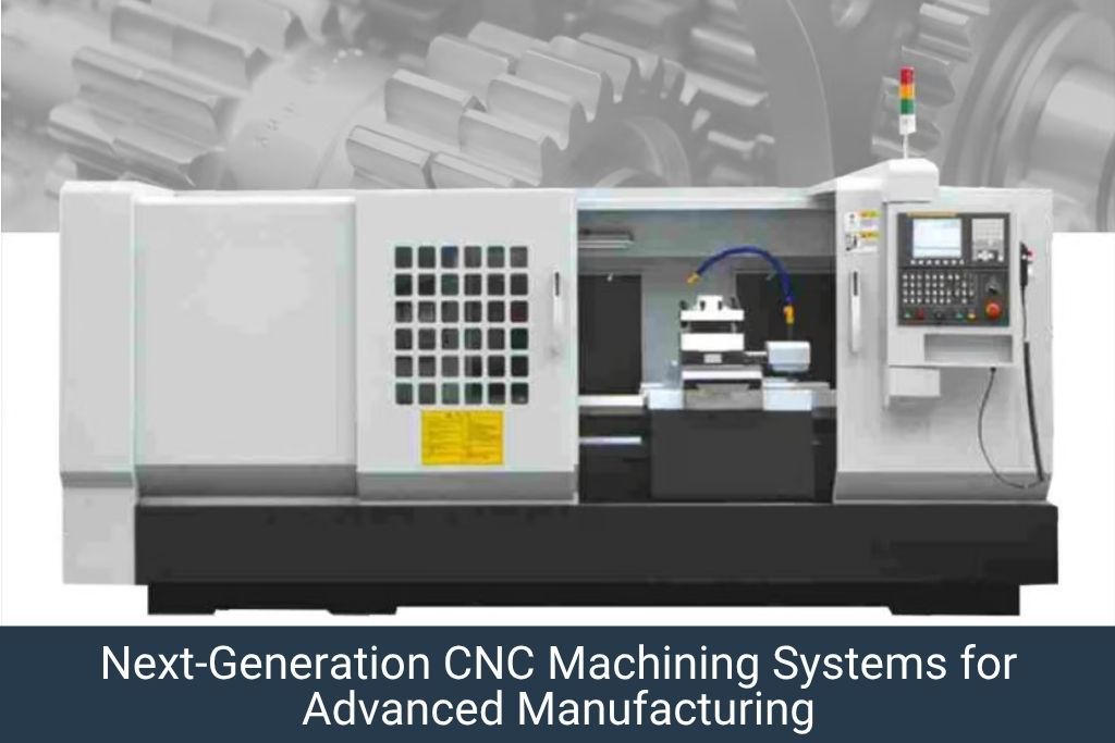
Advanced CNC Machining Systems
Modern CNC machines are at the heart of contemporary manufacturing. Expected at INTER Expo 2026:
MultiAxis CNC Lathes: Offering simultaneous machining capabilities that reduce production time and improve precision
5Axis CNC Milling Machines: Essential for complex component manufacturing in aerospace and medical device industries
HighSpeed Machining Centers: Enabling faster production cycles without compromising accuracy
Turning and Milling Combinations: Integrated systems that perform multiple operations in a single setup, reducing handling time and improving dimensional accuracy
Precision Engineering & Metrology Solutions
As industries demand tighter tolerances and higher quality standards:
Advanced Measurement Systems: Coordinate Measuring Machines (CMMs) and optical inspection systems for quality assurance
Surface Finishing Equipment: Grinding machines, honing equipment, and polishing systems for achieving superior surface finishes
Tool Presetting Technology: Automated tool measurement and presetting to reduce setup time and improve accuracy
Automation & Industry 4.0 Integration
The manufacturing sector is rapidly embracing smart manufacturing and digital transformation:
Robotic Integration: Collaborative robots (cobots) for material handling, machine tending, and assembly operations
IoTEnabled Machines: Equipment with realtime monitoring, predictive maintenance, and production analytics
Manufacturing Execution Systems (MES): Software solutions for production planning, tracking, and optimization
Digital Twins & Simulation: Virtual manufacturing environments for process optimization before actual production
Sheet Metal & Fabrication Technologies
For fabrication and sheet metal industries:
Advanced Press Systems: Hydraulic and servoelectric presses with enhanced precision and faster cycle times
Laser Cutting & Welding Systems: Highprecision laser technology for complex cutting and joining operations
Bending & Forming Equipment: Automated systems for sheet metal bending with superior accuracy and repeatability
Decoiling & Material Handling: Integrated systems for efficient material flow in fabrication shops
Sustainable & Green Manufacturing Solutions
Environmental consciousness is reshaping industrial practices:
EnergyEfficient Machines: Equipment designed to reduce power consumption while maintaining productivity
Waste Reduction Technologies: Systems that minimize material waste through precision engineering
EcoFriendly Coolants & Lubricants: Sustainable alternatives to traditional cutting fluids
Recycling & Scrap Management: Systems for efficient handling and recycling of manufacturing waste
Specialized Equipment for Emerging Sectors
Industries like aerospace, medical devices, and EV manufacturing have unique requirements:
Why Buyers, Manufacturers, and Industrial Professionals Should Visit INTER Expo 2026
For Factory Owners and Plant Managers
Operational Excellence Through Technology: Whether you operate a precision engineering shop, automotive component manufacturer, or general fabrication facility, INTER Expo 2026 offers opportunities to:
Identify equipment solutions for production bottlenecks
Explore automation options to enhance productivity
Evaluate machinery that can improve product quality and consistency
Connect with suppliers for equipment upgrades and replacement machinery
Understand the latest manufacturing trends in your industry
Investment Decision Making: Purchasing machinery is a significant capital investment. By visiting INTER Expo, you can:
Compare machines from multiple manufacturers sidebyside
Observe live demonstrations and technical specifications
Interact directly with equipment suppliers and technical experts
Negotiate pricing and explore financing options
Make informed decisions backed by industry insights
What Our Customers Say
“Our production speed has improved ever since we got a Bhavya machine. It’s smooth, durable, and works exactly as promised.”
Arti Mishra On Google
For Procurement Teams & Sourcing Professionals
Streamlined Vendor Selection: Instead of approaching equipment vendors individually, INTER Expo consolidates suppliers under one roof, enabling:
Comprehensive evaluation of available options
Assessment of technical capabilities and company credentials
Direct negotiation with decisionmakers and technical teams
Building longterm relationships with reliable suppliers
Accessing competitive pricing through concentrated supplier engagement
International Sourcing Opportunities: For companies interested in importing machinery:
Connect with international manufacturers and dealers
Understand import regulations, warranties, and aftersales support
Explore technology partnerships and distribution opportunities
Access machinery with international certifications and standards compliance
For Automotive & Aerospace Manufacturers
These sectors demand exceptional precision, repeatability, and quality assurance:
Precision Verification: See equipment capable of meeting automotive (ISO/TS 16949) and aerospace (AS9100) standards
Supply Chain Optimization: Connect with component suppliers and equipment manufacturers to strengthen your supply chain
Technology Roadmap: Understand where manufacturing technology is headed and plan your equipment strategy accordingly
Certification & Compliance: Learn about machinery that meets specific industry certifications and quality management systems
For Fabrication & Metalworking Companies
The fabrication sector encompasses diverse sub-industries, from structural steel to precision components:
Equipment Diversity: Explore solutions across the entire fabrication spectrum—cutting, bending, forming, welding, and finishing
Production Efficiency: Identify machinery that reduces waste, improves cycle times, and enhances output consistency
Skill Augmentation: Automation equipment that compensates for skill shortages in the fabrication industry
Quality Enhancement: Advanced metrology and inspection equipment that ensures consistency in finished products
For Tool Rooms & Job Shops
Tool rooms and job shops require extreme flexibility and precision:
Universal Equipment: Identify versatile machines capable of handling diverse job requirements
QuickChange Systems: Explore equipment with rapid setup and changeover capabilities
Precision Standards: Ensure machinery meets tight tolerance requirements of diverse clients
Technical Support: Connect with suppliers who understand tool room challenges and can provide specialized support
For Engineering & Construction Companies
Infrastructure and construction industries increasingly rely on precision-engineered components:
Component Manufacturing Capabilities: Explore equipment for inhouse component manufacturing
Customization Options: Connect with suppliers offering customizable machinery for specialized applications
Cost Optimization: Evaluate equipment investments that balance capital expenditure with operational efficiency
For Entrepreneurs & Startups
New manufacturing entrepreneurs benefit significantly from INTER Expo:
Business Model Validation: See successful manufacturing operations and learn best practices
Equipment Selection for New Ventures: Identify costeffective machinery suitable for startup scenarios
Financial Planning Support: Understand equipment pricing, ROI calculations, and financing options
Industry Networking: Build relationships with established players in your chosen manufacturing sector
Knowledge Acquisition: Gain insights from industry experts through seminars and technical discussions
How Bhavya Machine Tools Supports Industrial Growth & Manufacturing Excellence
With over 30 years of industry experience, Bhavya Machine Tools has established itself as a trusted partner for manufacturing industries across India and internationally. Our comprehensive portfolio addresses the complete spectrum of manufacturing challenges:
Our Expertise & Commitment
Three Decades of Excellence: Since its inception, Bhavya has been dedicated to helping manufacturers enhance their production capabilities, improve product quality, and optimize operational efficiency. We understand the unique challenges of Indian manufacturing—from the complexity of diverse industrial requirements to the importance of cost-effective solutions without compromising on quality.
ISO 9001:2015 Certified: Our commitment to quality and customer satisfaction is backed by international certification, ensuring that every machine delivered meets rigorous quality standards.
Customer-Centric Approach: We don’t just sell machines; we provide solutions. Our team works closely with customers to understand their specific requirements, challenges, and long-term manufacturing goals.
Comprehensive Machine Tool Portfolio
Our extensive range of industrial machinery caters to virtually every manufacturing need:
CNC Machines & Precision Equipment
CNC Lathes: From basic turning operations to complex multiaxis configurations with live tooling capabilities
CNC Milling Machines: Vertical, horizontal, and universal milling centers for precision component manufacturing
MultiAxis CNC Centers: Integrated turning and milling for reduced setup time and enhanced accuracy
CNC Drilling Machines: Highprecision drilling equipment for aerospace, automotive, and medical applications
Conventional & Manual Machines
Conventional Lathes: Robust machines for production turning, maintenance work, and tool room applications
Radial Drilling Machines: For large and heavy components requiring versatile drilling capabilities
Precision Drilling Machines: Pinpoint accuracy for demanding drilling applications
Pedestal Grinding Machines: Essential for surface finishing and tool sharpening
Hydraulic & Power-Operated Equipment
Hydraulic Presses: For forming, punching, blanking, and assembly operations in sheet metal and fabrication
Hydraulic Shears: For precise cutting of various materials and thicknesses
Hydraulic Brakes: For bending sheet metal with exceptional accuracy
Power Presses: For highspeed production operations in automotive and appliance manufacturing
Sheet Metal Fabrication Solutions
Hydraulic Press Brakes: Servo controlled and conventional systems for precise bending operations
Guillotine Shears: For accurate sheet metal cutting
Decoiling & Straightening Equipment: For automated material preparation in fabrication shops
Specialized & Purpose-Built Equipment
Gear Cutting Machines: Hobbing, shaping, and grinding equipment for precision gear manufacturing
Woodworking Machinery: Industrial solutions for furniture, door frame, and wooden product manufacturing
Welding Equipment: Manual and semiautomatic solutions for various welding applications
Custom Engineered Solutions: Tailormade equipment for unique manufacturing requirements
Solutions for Diverse Industries
Automotive Sector: Precision components, fasteners, and assemblies demand machinery capable of consistent accuracy and high production volumes. We supply equipment that meets automotive standards (ISO/TS 16949) and supports just-in-time manufacturing.
Aerospace Manufacturing: The aerospace industry requires uncompromising precision and traceability. Our equipment meets aerospace standards (AS9100) and supports the strict quality requirements of flight-critical components.
Fabrication & Steel Industries: From structural steel to precision fabricated components, we provide machinery for cutting, forming, bending, and finishing operations across diverse fabrication requirements.
Engineering & Manufacturing Companies: General manufacturing facilities benefit from our versatile equipment range and customization capabilities.
Metalworking & Job Shops: Our machines support the flexibility and precision requirements of job shops serving diverse industries.
Foundry & Metal Casting: Equipment for post-casting operations, including grinding, drilling, and finishing of cast components.
Tool Rooms & Model Making: Precision equipment essential for tool manufacturing, die making, and prototype development.
Medical & Pharmaceutical: Sterile, precision-engineered equipment for medical device and pharmaceutical component manufacturing.
Construction & Heavy Engineering: Equipment for manufacturing structural components, heavy machinery parts, and infrastructure-related products.
Key Differentiators
Technical Consultation & Custom Engineering
We don’t provide one-size-fits-all solutions. Our technical team works closely with customers to:
Assess current production capabilities and identify bottlenecks
Design equipment configurations tailored to specific manufacturing requirements
Optimize machine parameters for maximum productivity and quality
Plan phased implementation for minimal production disruption
Comprehensive After-Sales Support
Equipment purchase is just the beginning. We provide:
Installation & Commissioning: Expert setup ensuring optimal machine performance from day one
Operator Training: Comprehensive training for your production teams to maximize equipment utilization
Maintenance Support: Regular maintenance packages and emergency service support
Spare Parts Management: Easy access to genuine spare parts with efficient inventory management
Continuous Technical Support: Ongoing assistance for optimization and troubleshooting
Performance Monitoring: Regular checkins to ensure equipment performs to expectations
Quality Assurance & Reliability
Every machine undergoes rigorous testing before delivery:
Performance guarantees backed by service agreements
Warranty coverage for components and workmanship
Regular performance audits to track machine health
Cost-Effective Solutions
We understand budget constraints:
Machinery options across price points for different investment capacities
Refurbished and secondhand equipment for costconscious buyers
Flexible financing and leasing options through partnerships
ROI calculation support to justify equipment investment
Presence & Reach
Domestic Market: Strong presence across major manufacturing hubs—Coimbatore, Chennai, Bangalore, Pune, Hyderabad, Greater Noida, Mumbai, and Gujarat.
International Markets: Serving customers in Middle East, South East Asia, Africa, and other regions with dedicated support structures.
Export-Oriented Services: Specialized support for export-focused industries with documentation, quality certifications, and international standard compliance.
Featured Machine Tools & Industrial Solutions at INTER Expo 2026
Bhavya Machine Tools will showcase a curated selection of machines and solutions specifically relevant to INTER Expo’s engineering and infrastructure focus:
Live Demonstrations
Experience the precision and productivity of our machines through live demonstrations:
CNC Precision Machining: Watch advanced CNC machines in action, demonstrating simultaneous multiaxis operations and complex component manufacturing
Sheet Metal Forming: See hydraulic press brakes and forming equipment creating precise bends and complex shapes
Automation Solutions: Observe integrated machine systems demonstrating productivity enhancements and reduced cycle times
Position your manufacturing operation for future competitiveness
Why Choose Bhavya Machine Tools
Proven Track Record
Three decades of delivering solutions to thousands of manufacturers across diverse sectors demonstrates our reliability, technical capability, and commitment to customer satisfaction.
Comprehensive Product Range
From basic conventional machines to advanced CNC systems, from hydraulic equipment to specialized machinery—we offer solutions for virtually every manufacturing requirement.
Customization & Engineering Capability
Rather than forcing customers into standard configurations, our engineering team designs solutions tailored to specific manufacturing requirements and constraints.
Transparent Pricing & No Hidden Costs
Honest communication about pricing, capabilities, and limitations. No exaggerated claims or surprise costs post-purchase.
Uncompromising Quality Focus
ISO 9001:2015 certification reflects our commitment to quality in manufacturing, customer service, and support.
Comprehensive After-Sales Support
We invest heavily in customer support because we recognize that machinery purchase is the beginning, not the end, of our relationship with customers.
International Standards Compliance
Equipment meeting global standards enables our customers to serve international markets and meet export-quality requirements.
Flexible Financing Options
We understand that capital equipment purchase is significant. We work with financing partners to provide flexible payment options.
Spare Parts Availability
Genuine spare parts readily available, with efficient inventory management ensuring minimal downtime.
Industry-Specific Expertise
Our team brings deep understanding of different manufacturing sectors, enabling contextual, relevant recommendations rather than generic suggestions.
How Industrial Exhibitions Help Buyers Make Better Investment Decisions
Manufacturing equipment purchases represent significant capital investments with long-term implications. Industrial exhibitions like INTER Expo 2026 facilitate better decision-making through:
Consolidated Supplier Access
Rather than visiting individual suppliers across different locations, exhibitions bring dozens of suppliers under one roof, enabling:
Comprehensive comparison of available options
Assessment of multiple manufacturers’ capabilities
Timeefficient evaluation of alternatives
Negotiation leverage through direct supplier competition
Visual & Technical Verification
Seeing machines in operation and speaking with technical experts provides:
Actual performance observation rather than relying on brochures
Realtime technical discussion and clarification
Assessment of build quality, materials, and engineering
Understanding of practical capabilities beyond theoretical specifications
Industry Trend Awareness
Exhibitions provide insight into:
Where technology is heading in your sector
Emerging trends and innovations reshaping manufacturing
Best practices from successful manufacturers in your industry
Futureproofing your equipment investments
Risk Mitigation
Direct interaction with equipment manufacturers, other buyers, and industry peers helps:
Verify claims through multiple sources
Understand postpurchase support and service quality
Learn from experiences of existing users
Make decisions backed by adequate information
Relationship Development
Long-term equipment relationships benefit from strong initial connections:
Building trust through facetoface interaction
Establishing communication channels for ongoing support
Understanding supplier reliability and responsiveness
Creating foundation for longterm partnership
Key Takeaways
INTER Expo 2026 in Coimbatore (June 4-8) is a landmark event for India’s manufacturing and engineering sectors. The exhibition serves as a concentrated platform where manufacturing industries, equipment suppliers, engineers, and procurement professionals converge to explore technological innovations, make informed equipment investments, and build industry relationships.
For manufacturing professionals: INTER Expo provides unparalleled opportunity to evaluate equipment options, interact with technical experts, understand industry trends, and make strategic decisions about manufacturing investments.
For Bhavya Machine Tools: The exhibition represents an ideal venue to showcase our comprehensive machinery portfolio, demonstrate technical capabilities, and connect with manufacturers seeking solutions that enhance productivity, precision, and manufacturing excellence.
Expected outcomes for visitors:
Clear understanding of available technology options
Informed equipment selection decisions backed by direct evaluation
Valuable networking with industry peers and service providers
Strategic insights for manufacturing investment planning
Service Support: Available across India and internationally
Bring your manufacturing requirements and specific challenges. Our team is prepared to deliver practical, tailored solutions backed by three decades of industry expertise.
FAQs
What types of machines will Bhavya display at INTER Expo 2026?
We showcase a comprehensive range including CNC lathes, CNC milling machines, conventional lathes, drilling machines, hydraulic presses, sheet metal equipment, and specialized industrial machinery. Live demonstrations will highlight our precision capabilities, productivity enhancements, and customization options.
How can I determine if Bhavya's machines are suitable for my manufacturing requirements?
Our technical team at the exhibition will discuss your specific manufacturing challenges, production volume requirements, precision levels, and budget constraints. Based on this discussion, we recommend machinery configurations that best match your needs.
Does Bhavya provide customized machinery solutions?
Yes, absolutely. Rather than one-size-fits-all approaches, our engineering team designs machinery configurations tailored to specific manufacturing requirements. We can customize machines for unique applications, production volumes, and space constraints.
What after-sales support does Bhavya provide?
Comprehensive support including installation, operator training, regular maintenance, spare parts supply, technical troubleshooting, and ongoing performance monitoring. We work with customers as long-term partners, not just equipment suppliers.
Does Bhavya have presence in my region for service and support?
We maintain strong presence across major manufacturing hubs in India and serve international markets as well. During the exhibition, we can discuss service infrastructure in your specific location.
What financing options are available for equipment purchase?
We partner with various financial institutions to offer flexible financing options. Our team can discuss different payment plans suited to your capital investment capabilities.
How do I compare Bhavya machines with other manufacturers at the exhibition?
INTER Expo is specifically designed for this comparison. Visit multiple exhibitors, observe live demonstrations, discuss technical specifications, and evaluate options. Our team is happy to address any questions or concerns you raise.
Can I arrange a special demonstration focused on my specific manufacturing application?
Yes, we can schedule focused demonstrations addressing your particular manufacturing challenges. Contact us in advance or visit our stall to arrange this.
What is the typical ROI timeline for machinery investment?
ROI depends on your specific application, production volume, and current operation costs. Our team can calculate ROI for your specific scenario, typically ranging from 2-4 years for properly selected equipment.
How does Bhavya ensure machinery quality and precision?
Every machine undergoes rigorous pre-dispatch testing. We maintain ISO 9001:2015 certification, provide performance guarantees backed by service agreements, and include comprehensive warranty coverage. Our commitment to quality is evident through our 30-year track record.
HIMTEX 2026 in Hyderabad represents South India’s premier platform for manufacturing excellence, precision engineering, and industrial innovation. Taking place August 20-24, 2026, at HITEX Exhibition Centre, Hyderabad, this prestigious event connects leading machine tool manufacturers, industrial equipment providers, and manufacturing professionals across the Southern States and beyond. Hyderabad’s emergence as a significant manufacturing and technology hub, combined with its strategic location serving Telangana, Andhra Pradesh, Tamil Nadu, and Karnataka, makes HIMTEX 2026 an essential platform for manufacturers, exporters, and procurement professionals seeking cutting-edge machinery and industrial solutions. Bhavya Machine Tools participates actively, presenting comprehensive precision engineering solutions designed to help Southern India’s manufacturing sector achieve world-class productivity, quality, and competitiveness.
Introduction
South India has emerged as a powerhouse of manufacturing excellence. With established industrial centers in Bangalore, Pune, Coimbatore, Chennai, and increasingly in Hyderabad itself, the region hosts some of India’s most advanced manufacturing operations, from automotive giants to aerospace suppliers to precision engineering firms. As this manufacturing ecosystem continues to mature and expand, the demand for advanced machinery, precision equipment, and modern manufacturing solutions has never been greater. HIMTEX 2026 in Hyderabad emerges as the definitive platform where Southern India’s manufacturing community converges to explore industrial innovation, evaluate machinery investments, and connect with reliable equipment suppliers.
Scheduled for August 20-24, 2026 at the world-class HITEX Exhibition Centre, HIMTEX 2026 promises to be a landmark event showcasing the breadth and depth of India’s manufacturing technology landscape. This exhibition brings together hundreds of exhibitors ranging from established machine tool manufacturers to emerging automation specialists, providing a comprehensive platform for manufacturing professionals, factory owners, procurement teams, engineers, and industrial entrepreneurs to discover solutions that can transform their operations.
Bhavya Machine Tools, with over 30 years of experience delivering precision engineering solutions across South India and beyond, will showcase its comprehensive range of machinery at Hall No. 1, Stall No. 1B10. Whether you’re looking to upgrade your production equipment, explore automation options, identify specialized machinery for unique applications, or build relationships with proven equipment suppliers, HIMTEX 2026 offers the ideal opportunity to connect with technical expertise and proven manufacturing solutions.
What is HIMTEX 2026?
HIMTEX (Hyderabad International Machine Tool Exhibition) is South India’s premier international platform for machine tools, precision engineering equipment, and industrial machinery. As a comprehensive showcase of manufacturing technology, HIMTEX 2026 brings together:
Exporters & International Traders: Companies serving domestic and international markets seeking global standard equipment
Industrial Services Providers: Maintenance services, training providers, and manufacturing support specialists
HIMTEX 2026 is distinctly positioned as an international exhibition serving not just India’s manufacturing sector, but also attracting participating equipment suppliers from across the globe and buyers from various international markets.
South India hosts several of India’s most significant manufacturing and technology clusters:
Bangalore: India’s aerospace, automotive, and IT hardware manufacturing hub, hosting global companies and precision engineering firms
Coimbatore: The “Manchester of South India” with thousands of precision engineering companies and textile machinery manufacturers
Chennai: Major automotive hub and industrial manufacturing center with established supply chains and skilled workforce
Pune: Advanced automotive and engineering manufacturing center with numerous component suppliers and precision firms
Hyderabad: Rapidly emerging as a manufacturing and technology hub with growing aerospace, automotive, and pharmaceutical manufacturing
This manufacturing ecosystem represents extraordinary opportunity for equipment suppliers and customers alike.
The Strategic Importance of HIMTEX 2026
Regional Hub Function: Hyderabad’s location makes it the natural gathering point for manufacturers across Telangana, Andhra Pradesh, Karnataka, Tamil Nadu, and beyond.
Technology Leadership: Hyderabad’s growth as an aerospace and advanced manufacturing center makes it ideal for showcasing cutting-edge technology.
International Connectivity: As an international exhibition, HIMTEX attracts global equipment manufacturers and international buyers, enabling worldwide business connections.
Industry Diversity: South India’s diverse manufacturing base-from automotive to aerospace to precision engineering-creates rich opportunity for exhibitors and visitors.
Skills & Expertise: The region’s concentration of manufacturing talent and technical expertise makes it ideal for advanced technology showcasing and technical discussions.
Manufacturing Growth Drivers in South India
Several factors are driving accelerated manufacturing growth:
Government Support: Both Central and State governments are promoting manufacturing through special economic zones, industrial parks, and policy support
Multinational Company Presence: Major global manufacturers have established operations in the region, creating supply chain opportunities
Skilled Workforce Availability: Educational institutions and established manufacturing base provide access to skilled technical workforce
Export Orientation: South India’s manufacturing sector has strong export presence, demanding world-class equipment and capabilities
Supply Chain Integration: Well-developed supply chains enable just-in-time manufacturing and efficient production operations
HIMTEX 2026 provides the ideal platform for manufacturers to access equipment supporting this growth and leverage regional strengths.
Key Technologies & Industrial Trends Expected at HIMTEX 2026
Precision CNC Systems for Aerospace & Complex Manufacturing
South India’s aerospace sector creates demand for specialized precision equipment:
Aerospace Grade CNC Centers: Multiaxis systems meeting AS9100 standards for flight critical components
Large Scale Precision Machining: Equipment for significant component manufacturing without precision compromise
Specialized Tooling: Custom fixtures and holding devices for unique aerospace components
Quality Assurance Integration: Built in measurement and verification capabilities ensuring compliance
Automotive Precision Equipment
South India’s automotive manufacturing presence drives demand for specialized automotive solutions:
HighVolume Precision Lathes: Optimized for automotive component production with rapid changeover
MultiFunction Turning Centers: Integrated operations reducing part handling and improving consistency
ISO/TS 16949 Compliant Equipment: Systems supporting automotive quality standards and documentation
JustInTime Manufacturing Support: Equipment enabling rapid product changeovers and varied production scheduling
Precision Engineering for Specialty Manufacturing
From pharmaceutical to medical devices to industrial components:
Ultra Precision Equipment: Micron level accuracy for demanding applications
Specialized Workholding: Custom solutions for unique component geometries
Connect with suppliers supporting quality excellence
For International Exporters
Global Quality Standards: International markets demand specific certifications:
Verify equipment capabilities meeting international standards
Connect with suppliers experienced in export markets
Explore equipment supporting international quality certifications
Build relationships with suppliers supporting global ambitions
Supply Chain Development: International success requires reliable suppliers:
Identify equipment suppliers with international support networks
Evaluate global spare parts availability
Connect with suppliers experienced in international markets
Build long term partnerships supporting export growth
What Our Customers Say
“Largest Display of Machinery across India. Wide range of Machines. Very Co-operative staff. Range of Tapping Machine and Re-sharpening Machines are outstanding. Very Cost effective and useful in Precision Machining Work. Their staff is co – operative for after sales support.”
Bhavya Machine Tools brings 30+ years of manufacturing solution expertise specifically adapted to South India’s unique manufacturing ecosystem. We understand the region’s industries, challenges, competitive environment, and growth opportunities. This deep regional understanding shapes how we serve customers.
Our Commitment to South Indian Manufacturing
Deep Regional Roots: Our presence across South India—from Coimbatore to Bangalore to Chennai to Hyderabad—reflects commitment to the region’s manufacturing community.
Industry-Specific Expertise: Three decades of serving diverse industries (automotive, aerospace, precision engineering, fabrication) enables contextual recommendations tailored to your sector.
Technical Excellence: ISO 9001:2015 certification demonstrates our commitment to quality across manufacturing, customer service, and support.
Partnership Philosophy: We view customer relationships as long-term partnerships, not transactions ending at equipment delivery.
Comprehensive Product Portfolio Serving South Indian Manufacturing
Advanced CNC Machining Solutions
For precision manufacturing demanding complex component capabilities:
5 Axis CNC Machining Centers: Complex aerospace and precision components in single setup
High Speed Precision Lathes: Rapid production without precision compromise
Multi Function Turning Centers: Integrated turning and milling reducing setup time
Custom Built CNC Systems: Purpose engineered for specific applications and requirements
30+ years of serving South India’s manufacturing community demonstrates deep understanding of regional industries, challenges, and opportunities.
Comprehensive Equipment Range
From basic machines to advanced CNC systems, from conventional lathes to specialized equipment—comprehensive options addressing diverse manufacturing needs.
Advanced Technology Integration
While maintaining proven fundamentals, we continuously integrate latest innovations enabling competitive advantage.
Customization & Engineering Excellence
Rather than standard configurations, our engineering team designs solutions perfectly matched to your requirements.
ISO 9001:2015 Certification
Quality management systems certification ensures consistent excellence in manufacturing, service, and support.
Strong Regional Presence
Service centers and technical support across South India ensuring responsive support and quick problem resolution.
Industry-Specific Expertise
Deep understanding of different manufacturing sectors enabling contextual, sector-specific recommendations.
Uncompromising After-Sales Support
We invest heavily in customer support because equipment purchase begins, not ends, our relationship.
Flexible Financing & Leasing Options
Understanding capital equipment significance, we partner with financial institutions offering flexible terms.
International Standards Compliance
Equipment meeting global standards enabling businesses to serve international markets and meet export requirements.
Visit Bhavya Machine Tools at HIMTEX 2026 (August 20-24, 2026) at Hall No. 1, Stall No. 1B10, HITEX Exhibition Centre, Hyderabad.
Plan Your Exhibition Visit:
Consult with Our Technical Experts to discuss your manufacturing challenges and explore customized machinery solutions.
Experience Live Demonstrations of advanced CNC systems, precision equipment, and specialized manufacturing machinery.
Explore Customization Capabilities for your unique manufacturing requirements and production specifications.
Take Advantage of HIMTEX Special Offers including exclusive pricing, flexible financing, and premium service packages. Schedule Your Personal Consultation with technical specialists evaluating how advanced equipment can enhance your operations.
Regional Support: Strong presence across South India and international markets
Bring your manufacturing requirements and specific challenges. Our experienced team is prepared to provide tailored solutions backed by 30 years of manufacturing excellence and deep South India expertise.
FAQs
What is the scope of Bhavya's machinery showcase at HIMTEX 2026?
We showcase comprehensive solutions including precision CNC systems, aerospace-grade equipment, automotive components, hydraulic machinery, sheet metal fabrication equipment, and specialized manufacturing solutions. Live demonstrations will highlight precision capabilities, production efficiency, and customization options.
How does Bhavya support South India's manufacturing needs?
Through 30+ years of regional presence, we deeply understand South Indian industries' specific requirements. We serve automotive suppliers, aerospace manufacturers, precision engineers, fabricators, and general manufacturers with tailored solutions supported by strong regional service infrastructure.
Can Bhavya machines be customized for my specific manufacturing application?
Absolutely. Our engineering team designs machines tailored to your specific requirements—whether unique component geometry, specialized production volume, or industry-specific standards. Customization is a core competency, not exception.
What after-sales support does Bhavya provide in South India?
Comprehensive support including installation, operator training, maintenance programs, 24/7 technical support, genuine spare parts, and ongoing performance optimization. We maintain strong presence across South India for responsive, efficient support.
Does Bhavya supply equipment meeting international standards?
Yes. We supply equipment meeting AS9100 (aerospace), ISO/TS 16949 (automotive), and other international standards. Our team ensures equipment specifications and certifications meet your industry requirements.
What is typical ROI for machinery investment?
ROI depends on your specific application and current operations. Our team calculates realistic ROI for your scenario, typically ranging from 2-4 years for properly selected equipment in appropriate applications.
Are financing options available for equipment purchase?
Yes, we partner with financial institutions offering flexible financing and leasing options. Our team can discuss different payment plans suited to your capital investment capabilities.
How does Bhavya support automation implementation?
We provide comprehensive automation support including assessment, system design, equipment selection, integration support, and operator training. Our team works with your operation to develop automation strategies delivering genuine business value.
Can refurbished equipment be provided if budget is a constraint?
Yes, we offer quality refurbished and used machinery at significantly lower cost than new equipment. All refurbished machines undergo comprehensive testing and include warranties.
How can I best prepare for a visit to your stall at HIMTEX 2026?
Prepare by identifying your key manufacturing challenges, production volumes, precision requirements, and budget parameters. Bring this information to discuss with our technical team, enabling detailed, relevant recommendations tailored to your specific situation.
AMTEX 2026 in Greater Noida represents India’s premier platform for advanced manufacturing technology, industrial automation, and precision engineering innovation. Taking place July 24-27, 2026, at India Expo Mart, Greater Noida, this exhibition connects leading machine tool manufacturers, automation specialists, and industrial buyers in a comprehensive showcase of manufacturing excellence. With Greater Noida’s strategic location serving the National Capital Region and Northern India’s industrial heartland, AMTEX 2026 attracts domestic and international manufacturers, exporters, fabrication enterprises, and procurement professionals. Bhavya Machine Tools participates actively, presenting comprehensive machinery solutions designed to help manufacturers embrace automation, enhance precision, optimize productivity, and achieve competitive advantage in domestic and global markets.
Introduction
India’s manufacturing sector stands at an inflection point where automation, precision engineering, and smart manufacturing solutions have transitioned from luxury to necessity. As global competition intensifies and customer expectations for quality, delivery, and customization increase, manufacturing businesses across automotive, fabrication, aerospace, medical devices, and general engineering sectors recognize that equipment upgrades are critical investments in their competitive future. AMTEX 2026 in Greater Noida emerges as the quintessential platform where manufacturing leaders, technology innovators, and industrial entrepreneurs converge to explore the future of advanced manufacturing and industrial automation.
Hosted at the expansive India Expo Mart from July 24-27, 2026, AMTEX 2026 represents a unique opportunity for manufacturers, engineering professionals, procurement teams, and business leaders to stay at the forefront of manufacturing innovation. This exhibition showcases advanced CNC machining systems, automation solutions, Industry 4.0 technologies, precision measurement equipment, and specialized industrial machinery from hundreds of exhibitors. For any manufacturing professional seeking to enhance operational efficiency, improve product quality, or position their business for future growth, AMTEX 2026 is an unmissable event.
Bhavya Machine Tools, with 30+ years of expertise delivering precision engineering solutions, will be showcasing its comprehensive range of advanced machinery and automation solutions at Hall No. 9, Stall No. A-29. Whether you’re evaluating CNC systems for complex component manufacturing, exploring automation options for your production line, searching for specialized equipment for your niche manufacturing sector, or building relationships with reliable equipment suppliers, Bhavya’s presence at AMTEX 2026 offers direct access to technical expertise and proven manufacturing solutions.
What is AMTEX 2026?
AMTEX (Advanced Manufacturing & Technology Exhibition) is India’s premier trade show dedicated to advanced manufacturing technologies, industrial automation, and precision engineering solutions. As a comprehensive platform for manufacturing innovation, AMTEX 2026 brings together:
Advanced Machine Tool Manufacturers: Suppliers of CNC machines, multiaxis systems, highspeed machining centers, and precision equipment
Automation & Robotics Specialists: Companies offering robotic integration, collaborative robots (cobots), automated material handling, and manufacturing automation
Industry 4.0 Solution Providers: IoTenabled equipment, MES (Manufacturing Execution Systems), digital twins, predictive maintenance, and smart factory solutions
Industrial Equipment Providers: Hydraulic systems, pneumatic equipment, power transmission components, and specialized machinery
Industrial Buyers & Procurement Professionals: Factory owners, plant managers, procurement teams, and engineering professionals from manufacturing companies
Exporters & International Traders: Companies seeking equipment for international markets and global supply chain development
Technology Integration Partners: Companies offering CAD/CAM software, machine control systems, and manufacturing intelligence solutions
This exhibition is distinctly focused on advanced technologies and manufacturing innovation, distinguishing it from general machinery shows through emphasis on automation, precision, and next-generation manufacturing solutions.
India’s manufacturing sector faces a critical challenge: competing globally while managing cost structures that are increasingly difficult to maintain through labor-intensive operations alone. AMTEX 2026 directly addresses this challenge by:
Showcasing Automation Solutions: The exhibition features advanced automation technologies that enable Indian manufacturers to:
Reduce labor dependency while maintaining or improving output
Improve consistency and reduce quality variation
Enable 24/7 production operations
Reduce operational costs through improved efficiency
Demonstrating Industry 4.0 Implementation: Rather than theoretical discussions, AMTEX shows practical applications of:
Greater Noida’s Strategic Importance in India’s Manufacturing Landscape
Greater Noida, part of the National Capital Region, has emerged as a major industrial hub with strategic significance:
Proximity to Delhi Market: Serving India’s largest metropolitan area and consumer market
Industrial Concentration: Thousands of manufacturing units in automotive, engineering, fabrication, and general manufacturing
Skilled Workforce: Access to educated workforce and technical talent in and around NCR
Logistics Advantage: Welldeveloped infrastructure, connectivity, and proximity to transportation hubs
Market Hub Function: Gateway to North Indian markets and international trade corridors
Diverse Manufacturing Base: Automotive component suppliers, precision engineering, fabrication, appliances, and general manufacturing
Hosting AMTEX in Greater Noida makes strategic sense as the exhibition serves not only the NCR’s extensive manufacturing base but also attracts visitors from across Northern India and international markets.
Key Technologies & Industrial Trends Expected at AMTEX 2026
Multi-Axis CNC Machining Systems
Modern manufacturing demands complex component capabilities that single-axis or two-axis machines cannot deliver. Expected innovations:
Connect with suppliers supporting diverse customer requirements
For Entrepreneurs & New Manufacturing Ventures
Technology-Smart Manufacturing: New manufacturers can leapfrog traditional approaches:
Evaluate advanced equipment from startup friendly suppliers
Explore automation enabling small scale manufacturing with large scale efficiency
Identify leasing options reducing initial capital requirements
Connect with suppliers supporting startup manufacturing ventures
Scalable Solutions: Equipment should grow with your business:
Evaluate modular equipment expandable as production grows
Identify suppliers flexible about purchase timing and capacity
Explore equipment supporting product range expansion
Connect with suppliers committed to long term support
What Our Customers Say
“Our production speed has improved ever since we got a Bhavya machine. It’s smooth, durable, and works exactly as promised.”
Arti Mishra On Google
How Bhavya Machine Tools Supports Manufacturing Excellence & Industrial Growth
Bhavya Machine Tools is more than an equipment supplier-we are a partner in your manufacturing transformation. With three decades of experience and deep understanding of Indian manufacturing, we provide solutions that address real manufacturing challenges while supporting your business growth.
Our Manufacturing Philosophy
We believe that great manufacturing isn’t just about having advanced equipment—it’s about having the right equipment, properly configured, expertly installed, and thoroughly supported. This philosophy guides everything we do.
Commitment to Excellence: Every Bhavya machine reflects our commitment to precision, reliability, and customer satisfaction. Our ISO 9001:2015 certification demonstrates this commitment across our entire organization.
Understanding Indian Manufacturing: We understand the unique challenges of Indian manufacturing—from managing diverse production requirements to balancing cost and quality. Our solutions reflect this deep understanding.
Long-Term Partnership Approach: We view customer relationships as partnerships lasting decades, not transactions ending at equipment delivery. Our extensive after-sales support reflects this perspective.
30+ years of delivering manufacturing solutions to thousands of customers demonstrates reliability, technical capability, and commitment to customer success.
Comprehensive Product Portfolio
From basic conventional machines to advanced CNC systems, from hydraulic equipment to specialized machinery—we offer solutions across the entire manufacturing spectrum.
Advanced Technology Access
While staying true to proven fundamentals, we continuously integrate latest technological innovations enabling competitive advantage.
Customization Capability
Rather than forcing customers into standard configurations, our engineering team designs solutions perfectly matched to your requirements.
ISO 9001:2015 Certification
Our quality management systems certification ensures consistent excellence in manufacturing, customer service, and support.
Uncompromising Support Philosophy
We invest heavily in after-sales support because we recognize that equipment purchase begins, not concludes, our relationship with customers.
Industry-Specific Expertise
Deep understanding of different manufacturing sectors enables contextual, relevant recommendations rather than generic suggestions.
Flexible Financing Options
We understand capital equipment is a significant investment and partner with financial institutions to offer flexible terms.
Genuine Spare Parts & Service
Complete support ecosystem ensuring minimal downtime and maximum equipment productivity throughout its operational life.
International Standards Compliance
Equipment meeting global standards enables your business to serve international markets and meet export-quality requirements.
Visit Bhavya Machine Tools at AMTEX 2026 (July 24-27, 2026) at Hall No. 9, Stall No. A-29, India Expo Mart, Greater Noida.
Plan Your Visit:
Meet Our Advanced Manufacturing Experts to discuss your production requirements, manufacturing challenges, and equipment needs.
Experience Live Equipment Demonstrations showcasing advanced CNC systems, automation solutions, and precision machinery in action.
Explore Customization Capabilities tailored to your specific manufacturing requirements and production specifications.
Get AMTEX Special Offers on equipment purchases, extended financing options, and premium service packages. Schedule a Technical Consultation with our specialists to evaluate how advanced machinery can enhance your manufacturing operations.
International Support: Available across UAE, USA, and other regions
Bring your manufacturing requirements and production challenges. Our experienced team is prepared to deliver tailored solutions backed by 30 years of manufacturing excellence.
FAQs
How can I determine the right equipment for my manufacturing operation?
Our technical team will discuss your specific manufacturing challenges, production volumes, precision requirements, current capabilities, and future growth plans. Based on this comprehensive understanding, we recommend equipment configurations that address your needs while optimizing your investment.
Does Bhavya offer automation integration services?
Yes, we provide comprehensive automation services including robotic integration assessment, automated material handling system design, production line optimization, and implementation support. Our team works with your operation to develop automation strategies that make economic sense.
What is the typical ROI timeline for advanced machinery investment?
ROI depends on your specific application, current operation costs, and automation level. Our team can calculate realistic ROI for your scenario, typically ranging from 2-3 years for well-selected equipment in appropriate applications.
Do you provide equipment meeting aerospace and automotive standards?
Absolutely. We supply equipment meeting AS9100 (aerospace), ISO/TS 16949 (automotive), and other industry-specific standards. Our team ensures equipment specifications and capabilities meet your industry's stringent requirements.
Can you help integrate new equipment with existing production systems?
Yes, integration is a core competency. We work with your existing operations to integrate new equipment seamlessly, modify workflows as needed, and optimize your complete production system.
What training and support do you provide with equipment purchase?
Comprehensive support including expert installation, operator training, maintenance training, preventive maintenance programs, spare parts support, 24/7 technical assistance, and ongoing performance optimization.
How do I evaluate equipment precision claims?
AMTEX provides the ideal venue for verification. See machines in operation, observe precision through live demonstrations, request third-party certifications, and discuss specifications with our technical team.
What makes Bhavya different from other equipment suppliers?
Our 30-year track record, comprehensive product range, customization capability, uncompromising after-sales support, and deep industry expertise set us apart. We're not just equipment suppliers—we're manufacturing partners committed to your long-term success.
The 11th edition of ELASIA – India’s most significant electrical and power exhibition – came alive at the Bangalore International Exhibition Centre from 14 to 17 May 2026. Spread across four massive halls and 2,21,000 sq. ft. of exhibition area, ELASIA 2026 brought together over 770 exhibitors, 50,000+ business visitors, and participants from six countries, creating a charged atmosphere of innovation, commerce, and industry leadership.
Amidst this electrifying backdrop, Bhavya Machine Tools stood tall – not just as an exhibitor, but as a brand that brought precision engineering, live machinery demonstrations, and genuine industry conversations to one of India’s most prestigious industrial stages.
For Bhavya Machine Tools, participation in industry exhibitions has never been a routine checkbox. It is a deliberate, strategic move rooted in the company’s founding philosophy. As Director Jatin Shah has long maintained, “Our constant endeavour is on how emerging technology can be brought to India. Being innovative is Bhavya’s ultimate strategy.”
ELASIA, as India’s leading electrical and power exhibition, represents a natural and powerful platform for this vision. The electrical and electronics sector is deeply intertwined with machine tools – from precision components used in switchgear manufacturing to the automated fabrication lines powering transformer production. Exhibiting at ELASIA allowed Bhavya to connect with a high-value audience of decision-makers, procurement heads, and engineers who understand the language of precision.
With over 50,000 visitors from across India and six participating countries, ELASIA 2026 offered Bhavya Machine Tools unmatched access to both domestic buyers and international industry stakeholders – making it one of the most valuable exhibition investments of the year.
The Bhavya Machine Tools Experience at ELASIA 2026
Live Demonstrations That Spoke Louder Than Brochures
The Bhavya Machine Tools stall was designed around one core principle: show, don’t tell. Live demonstrations of key machines were the centrepiece of the exhibition presence – allowing visitors to witness firsthand the precision, power, and reliability that define every Bhavya product.
From metal cutting and bending to laser marking and drilling, visitors experienced the full capability of Bhavya’s product range in action. The machines on display were selected to reflect the needs of the electrical manufacturing sector – covering applications in automotive sub-components, electrical enclosures, cable trays, switchgear housings, and more.
Big Conversations, Real Connections
Exhibitions are where deals are shaped and relationships are forged – and ELASIA 2026 delivered on both fronts for Bhavya Machine Tools. The stall attracted a strong footfall of qualified visitors: plant managers, production heads, procurement officers, and entrepreneurs who came not just to browse, but to have meaningful conversations about their manufacturing challenges.
The Bhavya team – equipped with deep product knowledge and a genuine commitment to solving customer problems – turned every conversation into an opportunity to understand requirements, recommend solutions, and build trust. As Co-Director Rohit Shah has often noted, “Customers’ requirement is paramount to us. When we get an inquiry and we do not have the required tool in our product portfolio, we immediately set up a team to study if that specific type of tool can be procured.”
This customer-first approach was palpable at the exhibition stall. Visitors were not met with sales pitches but with thoughtful, solution-oriented dialogue – a hallmark of Bhavya’s decades-long approach to business.
The four days of ELASIA 2026 were a testament to what happens when a dedicated team takes the floor with passion and purpose. The Bhavya team brought infectious energy to every interaction – whether it was guiding a first-time visitor through a live machine demo, engaging seasoned industry professionals in technical dialogue, or capturing the buzz of the exhibition floor in real time.
Behind every successful exhibition presence is a culture of teamwork, and Bhavya Machine Tools exemplified this at ELASIA 2026. From stall setup and logistics to visitor engagement and post-event follow-up, the entire team operated as a cohesive unit – driven by shared pride in the brand they represent.
Showcasing Innovation, Precision & the Future of Manufacturing
The product range on display at ELASIA 2026 reinforced Bhavya’s reputation as a comprehensive, one-stop solution provider for precision engineering. Key product categories showcased included:
Each machine on display was selected to demonstrate Bhavya’s ability to meet the evolving and increasingly sophisticated demands of Indian manufacturers – particularly in sectors such as automotive, electrical, infrastructure, and general engineering.
ELASIA 2026 is not a standalone milestone for Bhavya Machine Tools – it is the latest chapter in a rich tradition of exhibition participation that spans India and the Gulf region. From IMTEX – where Bhavya has participated more than 15 times – to international platforms like SteelFab in Sharjah and MachAuto Expo, the company has consistently demonstrated its commitment to being present where industry conversations happen.
Each exhibition has shaped Bhavya’s understanding of global manufacturing trends, informed its product development roadmap, and helped the company stay ahead of what Indian industry needs. ELASIA 2026 was no different – it reinforced Bhavya’s position as a forward-thinking, globally-aware machine tools company that is deeply invested in the growth of Indian manufacturing.
What Our Customers Say
“Largest Display of Machinery across India. Wide range of Machines. Very Co-operative staff. Range of Tapping Machine and Re-sharpening Machines are outstanding. Very Cost effective and useful in Precision Machining Work. Their staff is co – operative for after sales support.”
Tirth Bhojani On Google
ELASIA 2026: By the Numbers
A snapshot of the scale and significance of the event:
770+ Exhibitors from across India and internationally
50,000+ Business visitors over four days
6 Countries represented at the exhibition
2,21,000 sq. ft. of exhibition area across 4 halls
14–17 May 2026 at BIEC, Bangalore
11th edition of India’s premier electrical and power exhibition
As the curtains came down on ELASIA 2026, the Bhavya Machine Tools team left Bangalore with more than exhibition memories – they left with new relationships, fresh market insights, confirmed business inquiries, and an even stronger sense of purpose.
For a company founded on the belief that exhibitions are the best way to stay current, stay connected, and stay ahead, ELASIA 2026 was exactly what it was designed to be: a platform to grow. And grow Bhavya did – in visibility, in relationships, and in its standing as one of India’s most trusted names in precision machine tools.
With the third generation of the Shah family now stepping into the business – bringing creative ideas and new technology – the future of Bhavya Machine Tools is as dynamic and driven as ever. ELASIA 2026 was a proud moment for the team, for the brand, and for Indian manufacturing.
“Big conversations. Live demos. New connections. A powerful presence.”
Bhavya Machine Tools is a leading name in precision engineering and workshop machinery, headquartered in Ahmedabad, India, with an international office in Dubai, UAE. Founded and led by brothers Jatin Shah and Rohit Shah, Bhavya offers a comprehensive range of machine tools including CNC machines, laser cutting and marking machines, hydraulic presses, drilling machines, bandsaw cutters, shearing machines, and much more. With a commitment to innovation, reliability, and customer-first service, Bhavya has built a trusted reputation across domestic and international markets over several decades.
Purchasing a CNC panel bender machine is a significant capital investment and selecting the wrong manufacturer can translate into years of operational setbacks, poor after-sales support and costly downtime. With a growing number of panel bending machine manufacturers in India and globally, buyers must apply structured due diligence – not just assess machine specs on paper. This guide walks you through the key evaluation criteria every procurement decision-maker should apply before signing a purchase agreement.
Before shortlisting any supplier, confirm their legal standing, certifications and production capacity. A credible panel bender manufacturer will hold ISO certifications, CE compliance markings (for export markets) and documented manufacturing audits. Ask for references from existing customers who operate in your industry segment – not just testimonials, but verifiable contact details. Bhavya Machine Tools, for instance, maintains transparent documentation on its product range and client base, which is a standard practice buyers should expect from any serious supplier. Check whether the manufacturer has in-house R&D or solely resells OEM equipment, as this directly affects how quickly they can support technical modifications.
CNC Panel Bending Machine Specifications: Matching Capacity to Your Production Requirements
Many buyers make the mistake of evaluating a CNC panel bending machine purely on maximum bending length or tonnage. Instead, map the machine’s full specification sheet against your actual production matrix – material thickness range, bend radius tolerances, angle repeatability and cycle time per part. Request a live demonstration or a Factory Acceptance Test (FAT) with your own sheet metal samples. Confirm whether the machine supports DXF import, offline programming and automatic tool compensation, as these directly impact your shop floor productivity.
Panel Benders Technology Evaluation: Assessing Automation Depth and Flexibility
Not all panel benders are equal in terms of automation architecture. When evaluating suppliers, distinguish between semi-automatic models and fully integrated automatic panel bender solutions. An automatic CNC metal sheet panel bender typically incorporates a manipulator arm, back gauge system and integrated blank feeding – but the actual automation sequence varies significantly by manufacturer. Scrutinise whether the automation system is proprietary or based on third-party robotics and how it handles part re-gripping for complex geometries. Also evaluate whether the system supports unattended or lights-out operation and what sensors and safeguards govern sheet detection and collision prevention.
A flexible panel bender differentiates itself from conventional press brakes through its ability to form multi-bend parts in a single setup without manual repositioning. When assessing this capability, probe the tooling change time, maximum number of sequential bends per program and whether the blade system supports upward and downward bending in the same cycle. Ask the manufacturer to demonstrate forming of your most complex part profile. Evaluate the tool library management system – how many tool stations the machine holds and whether universal tooling is compatible with third-party inserts. A manufacturer that offers application engineering support for tooling optimisation is considerably more valuable than one that only supplies standard configurations.
Panel Bender Manufacturer Support Infrastructure: What Happens After Delivery
Post-installation support is where many panel bending machine manufacturers in India fall short. During supplier evaluation, specifically audit the following: availability of field service engineers within your region, average response time for breakdown calls, remote diagnostic capability via teleservice or connectivity and spare parts stocking policy. Request the standard mean time between failures (MTBF) data for critical components such as the servo drive, back gauge motors and bending blade actuators. Confirm whether the manufacturer offers a structured preventive maintenance contract with defined SLA terms. Bhavya Machine Tools, as a reliable supplier with an established domestic service network, is one example of how localised support can reduce machine downtime significantly compared to imported brands with thin service coverage.
Panel Bending Machine Manufacturers in India: Evaluating Domestic vs. Imported Options
Procurement teams often weigh domestic panel bending machine manufacturers in India against European or Taiwanese imports. The trade-off analysis should cover total cost of ownership – not just unit price. Domestic manufacturers typically offer faster delivery lead times, lower import duty exposure and easier access to on-site service. However, evaluate whether the domestic manufacturer’s CNC control and servo systems are indigenously developed or imported sub-assemblies, as this determines the actual reliability baseline. Look at the manufacturer’s installed base in your target application – automotive component fabrication, HVAC panel production, electrical enclosure forming or elevator panel manufacturing – each of which has distinct accuracy and throughput demands.
A credible supplier will provide itemised quotations that clearly separate machine cost, tooling package, installation and commissioning, operator training and annual maintenance contract (AMC) pricing. Be cautious of manufacturers who bundle everything into a single lump-sum figure, as this obscures the true cost of ownership. Confirm the warranty scope in writing – specifically which components are covered, what constitutes warranty exclusions and the process for warranty claims. Also clarify the terms for software updates and CNC controller licensing, as some suppliers charge separately for firmware upgrades.
Choosing the right CNC panel bender machine manufacturer requires a structured evaluation process that goes well beyond comparing brochure specifications. Buyers must assess technical depth, automation architecture, tooling flexibility, post-sale support infrastructure and software integration readiness in parallel. Bhavya Machine Tools demonstrate that domestic manufacturers can meet these criteria competitively when buyers apply the right due diligence framework. Align your procurement decision with long-term operational needs, not just upfront acquisition cost, to maximise the return on your capital investment.
What certifications should a reliable panel bender manufacturer hold?
Look for ISO 9001 certification, CE compliance for export-standard machines and documented Factory Acceptance Test procedures - these confirm the manufacturer meets established quality and safety benchmarks.
How do I evaluate an automatic CNC metal sheet panel bender before purchase?
Request a live demonstration using your own material samples and verify automation sequences, sensor safeguards and offline programming compatibility with your existing CAD/CAM software.
What distinguishes a flexible panel bender from a standard press brake?
A flexible panel bender performs multi-bend sequences in a single setup without repositioning, supports upward and downward bending in the same cycle and significantly reduces part handling time on complex profiles.
How should I compare panel bending machine manufacturers in India against imported brands?
Evaluate total cost of ownership - factoring in import duties, spare parts lead time, service network density and controller ecosystem compatibility - rather than focusing solely on unit price.
What after-sales support terms should I confirm before buying a CNC panel bending machine?
Confirm field service response time SLAs, remote teleservice capability, spare parts availability timelines, preventive maintenance contract terms and whether critical consumable components are stocked locally.
Panel bending technology has significantly evolved in modern sheet metal fabrication. Two configurations dominate today’s precision bending landscape – the flexible panel bender and the automatic panel bender. While both serve the same fundamental purpose of shaping metal sheets, they operate on distinctly different principles, tooling logic and production philosophies. Understanding what separates these two systems helps manufacturers, fabricators and procurement teams make smarter capital investment decisions.
Flexible Panel Bender: What Makes This Configuration Truly Adaptable
A flexible panel bender is engineered to handle a wide variety of part geometries, material thicknesses and bend sequences without requiring a complete tooling changeover between jobs. The defining feature is its programmable blade and universal tooling system, which can adapt to different profiles through software-driven adjustments rather than manual retooling.
Unlike fixed-tooling setups, an automatic CNC panel bender can switch from one component profile to another within minutes. This agility is rooted in its modular blade segments, adjustable backgauges and CNC-controlled bending axes. The system reads a new part program, repositions relevant components automatically and executes the bend sequence – all with minimal operator involvement.
This configuration is particularly well-suited for job shops, contract manufacturers and production environments where batch sizes vary, part complexity is high or product changeovers are frequent. The flexibility is not just mechanical – it extends to how the machine interprets bend sequences, handles part repositioning and manages tolerance stacking across multi-bend profiles.
Bhavya Machine Tools, a well-regarded name in precision sheet metal machinery, offers flexible panel bender configurations designed to meet exactly these high-mix, low-to-medium volume demands, where tooling agility directly translates to reduced setup time and faster delivery cycles.
Automatic CNC Metal Sheet Panel Bender: How Fixed and Programmable Tooling Systems Differ
An automatic CNC metal sheet panel bender operates on a higher throughput principle. Here, the machine is typically optimized for a specific range of part families with defined material grades and repeat geometries. The tooling – upper and lower bending blades, clamping beams and backgauge – may be fixed or semi-fixed for a targeted production profile.
Where a flexible panel bender prioritizes changeover speed and geometry versatility, the automaticpanel bender prioritizes cycle time, repeatability and uninterrupted production volume. Its programmable CNC control manages the entire bending cycle – part feeding, clamping force, bend angle correction and part extraction – with near-zero manual intervention.
The “automatic” in this context refers specifically to the machine’s ability to handle part manipulation autonomously. Integrated sheet followers, robotic part handlers or suction-cup-based feeding systems keep the panel in controlled contact throughout each bend sequence. This reduces part distortion, maintains angular accuracy and enables lights-out or semi-lights-out manufacturing.
The key structural difference between programmable tooling systems and fixed tooling lies in reconfigurability. Programmable systems store tool positions, blade pressure profiles and bend sequences in digital programs – they are recalled and re-executed at the push of a button. Fixed tooling is ground or machined to a specific profile and must be physically swapped, which takes significantly more time and skilled labor.
Flexible Panel Bender Manufacturer: What to Look for in Tooling System Design
When evaluating a flexible panel bender manufacturer, the critical differentiator is not just machine build quality – it is the intelligence embedded in the tooling architecture. A well-designed flexible bender will feature independently controlled blade segments, real-time angle measurement feedback and offline programming compatibility with standard CAD/CAM platforms.
Look for machines that support automatic tool clamping, programmable crowning systems for deflection compensation and multi-axis backgauge systems capable of handling complex part repositioning. These features directly determine how wide a range of component profiles the machine can produce without manual intervention.
Bhavya Machine Tools designs its flexible panel bender systems with these core engineering considerations embedded – particularly for environments where quick changeover and consistent angular accuracy across varied batch profiles are non-negotiable production requirements.
Automatic Panel Bender: Which Production Environment Benefits Most
The automatic panel bender system is best matched to production environments with high part volume, stable product lines and low geometric variability. Think elevator panels, appliance housings, HVAC enclosures or electrical cabinet doors – parts produced in large quantities with consistent dimensions and material specifications.
In these settings, the machine’s fixed or semi-fixed tooling setup pays off rapidly. Setup time is a one-time investment per product family and subsequent production runs execute at full machine speed with no changeover overhead. The economic logic is simple: when part volume is high and part variety is low, tooling rigidity becomes an asset rather than a constraint.
Conversely, flexible panel benders deliver superior ROI in job shop environments, custom fabrication facilities and industries where part designs evolve frequently – such as architecture, industrial equipment and specialty enclosure manufacturing. The ability to switch between a simple single-bend bracket and a complex multi-flange housing within the same shift makes the flexible configuration economically superior in these contexts.
“Largest Display of Machinery across India. Wide range of Machines. Very Co-operative staff. Range of Tapping Machine and Re-sharpening Machines are outstanding. Very Cost effective and useful in Precision Machining Work. Their staff is co – operative for after sales support.”
Tirth Bhojani On Google
Programmable Tooling vs. Fixed Tooling: A Direct Comparison for Procurement Decisions
The core question for any fabrication manager evaluating these two systems is: what is the production profile over the next five years? If the answer involves increasing part variety, shorter lead times and more frequent design iterations, a flexible panel bender is the more scalable investment. If the answer involves growing volume on an established product range, an automatic CNC metal sheet panel bender with optimized fixed tooling will deliver lower per-part cost at scale.
Programmable tooling systems also offer a future-proofing advantage. As part designs change or new product lines are introduced, the machine adapts through software rather than capital reinvestment in new tooling sets. This is a material advantage in industries with accelerating design cycles.
The distinction between a flexible panel bender and an automatic panel bender ultimately comes down to how tooling is configured, how quickly it adapts and what production volume justifies each approach. Both systems rely on CNC precision and programmable control – the difference lies in the degree of tooling reconfigurability and the production environment each is engineered to serve. Companies like Bhavya Machine Tools offer configurations across both categories, ensuring fabricators can align machine capability with actual production demands rather than compromising either throughput or versatility.
FAQs on Flexible Panel Bender & Automatic Panel Bender
What makes a panel bender "flexible" compared to a standard automatic panel bender?
A flexible panel bender uses programmable, modular tooling that adapts to different part geometries without physical changeover, whereas a standard automatic panel bender typically uses optimized fixed tooling suited for high-volume, repeat production runs.
Automatic panel bender systems - can they handle complex multi-bend profiles efficiently?
Yes, automatic CNC metal sheet panel benders handle multi-bend profiles efficiently through stored CNC programs, but their efficiency peaks when part geometry remains consistent across large production batches rather than frequent design changes.
Key criteria include independently programmable blade segments, real-time angle feedback, multi-axis backgauge control, offline CAD/CAM compatibility and the manufacturer's after-sales support capability for tooling adjustments and software updates.
How do programmable tooling systems differ from fixed tooling in terms of changeover time?
Programmable tooling systems switch between part programs in minutes through CNC recall, while fixed tooling requires physical removal, replacement and realignment - a process that can take hours and requires skilled operator involvement.
Which industries benefit most from investing in a flexible panel bender over an automatic panel bender?
Job shops, custom enclosure fabricators, architectural metalwork producers and industrial equipment manufacturers benefit most from flexible panel benders due to high part variety, short batch sizes and frequent design updates that make fixed tooling setups economically inefficient.
The HVAC and ventilation duct manufacturing industry demands precision sheet metal components produced at high volume, with zero compromise on dimensional accuracy. A CNC panel bendermachine addresses this need directly – forming duct flanges, access door frames, damper housings and ventilation enclosures in a single, uninterrupted workflow without manual repositioning or die changes. As global demand for commercial HVAC systems, cleanroom ventilation and industrial exhaust infrastructure accelerates, duct fabricators are shifting to automated bending technology to stay competitive.
CNC Panel Bending Machine Role in Duct Flange Production
CNC panel bending machines are at the center of high-speed duct flange fabrication. Rectangular and circular duct flanges – TDC (Transverse Duct Connection) and TDF profiles – require tight angular tolerances across all four sides to ensure airtight assembly on-site. The automatic bending sequence programs all four bends on a single sheet blank, maintaining flange height and squareness without manual intervention between passes. For galvanized steel, aluminized steel and stainless duct-grade materials, consistent springback compensation is calculated automatically, eliminating the trial-and-error adjustment common to press brake operations. Production rates for standard rectangular duct flanges can reach several hundred units per shift, which conventional tooling setups cannot match.
Panel Benders Producing Access Door Frames for Air Handling Units
Access door frames for air handling units, fan coil enclosures and inline duct inspection panels are complex sub-assemblies with return flanges, rebates and hinge-mounting tips formed on all four edges. Panel benders handle this geometry in a programmed multi-bend cycle that would otherwise require multiple press brake setups and intermediate part handling. The flexible tooling system of a modern automatic CNC metal sheet panel bender accommodates varying door frame widths and heights through axis repositioning alone – no physical die swap is needed between different frame sizes. This is critical for HVAC manufacturers producing multiple AHU models on the same production line.
Automatic Panel Bender Forming Damper Housings and Blade Frames
Volume dampers, fire dampers and motorized control dampers require precisely formed housings and blade support frames where angular deviation directly impacts leakage performance and blade actuation. An automatic panel benderproduces the U-channel housing profiles and end bracket geometries in repeatable sequences, maintaining consistent leg height across the full part length – a dimension that controls blade-to-housing clearance. Multi-radius and compound bend profiles on damper end caps are programmed directly into the machine’s CNC controller, removing reliability on skilled operator judgment for each setup. For fire-rated damper assemblies, where geometric compliance is part of the certification requirement, this level of repeatability is non-negotiable.
A flexible panel bender supports rapid changeover between ventilation component families – grille frames, plenum boxes, supply air diffuser housings and exhaust fan transition pieces – without tooling changes. In a typical HVAC ductwork fabrication environment, the product mix shifts constantly based on project schedules. The ability to call up a saved bending program and run the next component in minutes, rather than hours of die setup, directly reduces work-in-progress inventory and lead times. Sheet thickness ranges from 0.5 mm for lightweight residential ductwork components to 3 mm or more for industrial exhaust and dust extraction systems – all handled within the same machine’s capacity range through programmable beam pressure control.
Panel Bending Machine Manufacturers in India Serving the HVAC Sector
Panel bending machine manufacturersin India have developed machines specifically suited to the sheet metal specifications used in domestic and export HVAC production. Bhavya Machine Tools is among the recognized names in this space, offering panel bending machines engineered for consistent performance across galvanized steel, stainless steel and aluminum alloys commonly used in ventilation duct manufacturing. With in-country availability of technical support, spare parts and application engineering, Indian manufacturers serve both large integrated HVAC OEMs and mid-scale duct fabrication shops. Procurement lead times and lifecycle costs are substantially lower compared to imported alternatives, making domestic sourcing an increasingly practical decision for expanding HVAC fabricators.
Panel Bender Manufacturer Selection Criteria for Duct Fabrication Applications
Choosing the right panel bender manufacturer for HVAC applications goes beyond machine specifications. Duct fabricators need application-specific bending programs for their standard component library, integration capability with CAD/CAM nesting software and after-sales support structured around production continuity. Key technical parameters include maximum bending length relative to the largest duct panel size in the product range, back-gauge positioning accuracy for flange height consistency and the machine’s ability to handle pre-punched or pre-notched blanks without part distortion. Bhavya Machine Tools provides application consultation alongside equipment supply, helping fabricators configure machines that align with their actual component mix rather than generic specifications.
What Our Customers Say
“Largest Display of Machinery across India. Wide range of Machines. Very Co-operative staff. Range of Tapping Machine and Re-sharpening Machines are outstanding. Very Cost effective and useful in Precision Machining Work. Their staff is co – operative for after sales support.”
Tirth Bhojani On Google
Automatic CNC Metal Sheet Panel Bender: Process Advantages in High-Mix Duct Production
In HVAC duct manufacturing, the challenge is not high-volume production of a single part – it is high-mix production of dozens of related components, each with slightly different dimensions and bend sequences. An automatic CNC metal sheet panel bender resolves this through programmable bending sequences stored as retrievable jobs. When an order batch for 200mm × 400mm rectangular duct flanges is followed by a batch of custom-sized access frames, the transition requires only a program recall and material load – not a physical setup cycle. Across a production week, this eliminates hours of downtime that accumulate in press brake-based operations, directly improving throughput without adding headcount.
The adoption of CNC panel bending machines in HVAC and ventilation duct manufacturing is driven by the industry’s requirement for dimensional consistency, process flexibility and production speed across a wide component range. From duct flanges and damper housings to access door frames and plenum enclosures, these machines deliver repeatable geometry in every cycle without tooling changes. Bhavya Machine Tools supports HVAC fabricators in this transition with machines built for the material grades, part sizes and production volumes specific to the ventilation sector.
How does a CNC panel bender machine produce duct flanges without tooling changes?
It uses programmable bending sequences and adjustable beam positioning to form all flange bends on a single blank, switching between different flange sizes by recalling saved programs rather than changing physical dies.
Can a panel bending machine handle galvanized steel used in HVAC ductwork?
Yes, automatic panel benders are designed to process galvanized steel, aluminized steel and aluminum sheet - the standard materials in ventilation duct manufacturing - with automatic springback compensation for each material type.
What makes a flexible panel bender suitable for high-mix HVAC component production?
Its ability to store and retrieve bending programs for different component profiles - flanges, damper housings, access frames - means changeover between part types takes minutes, not hours of die setup.
How do panel bending machine manufacturers in India support HVAC fabricators?
Manufacturers like Bhavya Machine Tools offer application-specific machine configuration, pre-loaded bending programs for common duct components and local technical support that reduces downtime risk in production environments.
What geometric accuracy does a CNC panel bending machine maintain for damper housings?
CNC panel benders maintain consistent leg height, angular accuracy and part squareness within tight tolerances across the full production batch, which is essential for damper housing geometry that controls blade clearance and leakage performance.
Cutting non-ferrous and stainless metals demands more than just raw power – it requires precise parameter control, the right assist gas and a deep understanding of each material’s thermal behaviour. A fiber laser cutting machine delivers the speed and accuracy needed for these metals, but only when configured correctly. This guide covers material-specific settings, gas selection and edge quality strategies to help you get the best results every time.
Fiber Laser Cutting Stainless Steel: Parameters, Gas and Edge Finish
Fiber laser cutting stainless steel is one of the most common industrial applications and for good reason – stainless responds predictably when parameters are dialled in correctly.
Power and Speed Settings: For stainless steel between 1–3 mm, a laser cutting machine running 1–2 kW with cutting speeds of 10–20 m/min delivers clean results. Thicker sheets (6–12 mm) require 3–6 kW with reduced speeds of 1–4 m/min. Higher wattage machines from Bhavya Machine Tools allow operators to push productivity without sacrificing cut quality.
Assist Gas – Nitrogen vs. Oxygen:
Nitrogen (N₂): Preferred for stainless steel. It acts as an inert purge gas, preventing oxidation at the cut edge. The result is a bright, oxide-free, weld-ready finish – critical for food-grade, medical and decorative applications. Nitrogen cutting typically requires higher pressures (10–20 bar) to eject molten material efficiently.
Oxygen (O₂): Creates an exothermic reaction that boosts cutting speed on thicker stainless, but leaves a dark, oxidised edge that needs post-processing. Best used when edge aesthetics are not a priority.
Edge Quality Tips:
Reduce cutting speed slightly on thicker gauges to avoid dross formation on the bottom edge.
Maintain a consistent focal point – for stainless, the focal position is typically set at or slightly below the surface.
Use a high-quality nozzle with a diameter matched to material thickness (1.5–2.5 mm for most stainless gauges).
Laser Cutting Aluminium: Overcoming Reflectivity and Thermal Challenges
Laser cutting aluminium presents unique challenges. Aluminium’s high reflectivity and thermal conductivity can cause beam back-reflection and inconsistent cut quality if the fibre laser cutting machine is not properly configured.
Power and Speed Settings: Aluminium requires higher power relative to its thickness compared to steel. For 1–2 mm aluminium, a 1.5–2 kW machine at speeds of 8–15 m/min is effective. For 6–10 mm sheets, 4–6 kW with speeds of 1–3 m/min is recommended. Modern fiber laser systems handle aluminium better than CO₂ lasers due to their shorter wavelength and superior absorption by the material.
Assist Gas Selection:
Nitrogen is strongly recommended for aluminium. It suppresses oxidation, keeps the cut zone clean and prevents the formation of aluminium oxide, which has a much higher melting point than the base metal and can cause rough edges and incomplete cuts.
Air cutting is possible on thin aluminium (≤2 mm) for non-critical parts where slight oxidation is acceptable and it significantly reduces operating costs.
Edge Quality Tips:
Ensure the cutting head is equipped with back-reflection protection, especially when processing highly polished or mirror-finish aluminium sheets.
Set focus position slightly below the surface (−1 to −2 mm) to compensate for thermal diffusion.
Use higher assist gas pressure (12–18 bar) to clear the melt zone effectively and reduce burr.
On an Exchange Table Fiber Laser Cutting Machine, rapid sheet changeover allows operators to process multiple aluminium batches without downtime – especially beneficial in high-volume sheet metal workshops.
Fiber Cutting Laser Machine Settings for Copper: Managing High Reflectivity
Copper is one of the most reflective metals and has extremely high thermal conductivity, making it one of the most challenging materials for any cutting machine. However, with the right fibre laser cutting machine configuration, clean cuts are achievable.
Power and Speed Settings: Copper demands high peak power. For 1 mm copper sheet, a minimum of 1.5–2 kW is required; for 3–4 mm, 4–6 kW is necessary. Cutting speeds are generally lower than for stainless – around 3–8 m/min for thin gauges due to the material’s heat dissipation characteristics.
Assist Gas Selection:
Oxygen can be used on copper to initiate an oxidation reaction that assists cutting, though it creates a darker edge finish.
Nitrogen at high pressure produces cleaner edges but requires sufficient laser power to compensate for the lack of exothermic assistance.
Edge Quality Tips:
Use a laser cutting machine with a high-brightness beam (single-mode or near single-mode) – beam quality directly impacts the ability to cut copper cleanly.
Pulsed cutting mode or burst mode helps initiate the cut and reduces back-reflection damage to optics.
Keep nozzle standoff distance minimal (0.5–1 mm) for better gas pressure delivery at the cut zone.
Piercing copper requires extra care – use a slow pierce with gradual power ramp-up to avoid splattering molten material onto the lens.
Fiber Laser Cutting Brass: Balancing Speed, Power and Gas Pressure
Brass, a zinc-copper alloy, presents moderate reflectivity but generates zinc fumes during cutting – a key health and process consideration. A well-configured fiber laser cutting machine handles brass effectively with appropriate ventilation and parameter settings.
Power and Speed Settings: For brass sheets between 1–3 mm, a 1–2 kW laser cutting machine running at 6–14 m/min is efficient. For 4–6 mm brass, 3–4 kW with speeds of 1.5–4 m/min provides acceptable cut quality. Bhavya Machine Tools’ fiber laser systems support programmable parameter profiles, allowing quick switching between brass gauges.
Assist Gas Selection:
Nitrogen is preferred for brass to prevent oxidation and deliver a smooth, burr-minimal edge – especially important for decorative and architectural brass components.
Air is viable for lower-precision cuts on thin brass, providing a cost-effective option for high-volume production.
Edge Quality Tips:
Ensure adequate fume extraction is in place – zinc vapour from brass cutting is hazardous and can contaminate optics over time.
Slightly increase cutting speed compared to copper for the same thickness, as brass has lower thermal conductivity.
For intricate brass profiles cut on a Tube Fiber Laser Cutting Machine, verify that the rotary chuck clamping pressure does not deform thin-wall brass tubes during processing.
What Our Customers Say
“Our production speed has improved ever since we got a Bhavya machine. It’s smooth, durable, and works exactly as promised.”
Arti Mishra On Google
Fiber Laser Cutting Machine Assist Gas: Nitrogen vs. Oxygen – When to Use Which
Across all four metals, assist gas selection is the single most important variable after laser power. Here is a concise reference:
Metal
Preferred Gas
Pressure Range
Edge Result
Stainless Steel
Nitrogen
10–20 bar
Bright, oxide-free
Aluminium
Nitrogen
12–18 bar
Clean, low-burr
Copper
Nitrogen / Oxygen
10–16 bar
Clean / oxidised
Brass
Nitrogen / Air
8–14 bar
Smooth / slight oxide
Oxygen accelerates cutting speed through exothermic reaction but compromises edge quality. Nitrogen preserves metallurgical integrity but requires higher pressure and operating cost. For precision parts, nitrogen is almost always the correct choice across all non-ferrous metals.
In production environments where stainless, aluminium, copper and brass sheets are processed in sequence, an Exchange Table Fiber Laser Cutting Machine delivers measurable throughput gains. The dual-pallet system allows one sheet to be loaded while another is being cut – eliminating idle time between jobs. Bhavya Machine Tools offers exchange table configurations that support this workflow, with automatic pallet changeover times under 15 seconds on select models.
Cutting stainless steel, aluminium, copper and brass on a fiber laser cutting machine requires material-specific power settings, precise focal positioning and the correct assist gas – nitrogen for quality-critical applications, oxygen or air where speed and cost take priority. Dross control, nozzle selection and beam quality are equally important for achieving consistent edge finishes. Bhavya Machine Tools provides fiber laser cutting solutions – including tube and exchange table variants – engineered to handle the full spectrum of non-ferrous and stainless metal cutting with the precision that modern fabrication demands.
FAQs
Which assist gas is best for fiber laser cutting stainless steel?
Nitrogen is the preferred choice as it prevents oxidation and delivers a bright, weld-ready edge - oxygen can be used on thicker gauges where edge aesthetics are not critical.
Why is aluminium difficult to cut on a laser cutting machine?
Aluminium's high reflectivity and thermal conductivity cause beam back-reflection and inconsistent cuts, requiring back-reflection protection and higher assist gas pressure for clean results.
What power settings are recommended for fiber laser cutting copper?
A minimum of 1.5–2 kW is needed for 1 mm copper, scaling up to 4–6 kW for 3–4 mm sheets, with pulsed pierce mode recommended to protect the cutting machine's optics.
Can a tube fiber laser cutting machine cut brass tubes accurately?
Yes, but rotary chuck clamping pressure must be carefully controlled to avoid deforming thin-wall brass tubes during the laser cutting process.
What is the productivity benefit of an exchange table fiber laser cutting machine in multi-material shops?
The dual-pallet system allows one sheet to load while another is being cut, eliminating idle time and enabling seamless switching between stainless, aluminium, copper and brass jobs.
Choosing the Right Threading Machine – Bolt Threading vs. Hydraulic Thread & Form Rolling
When selecting the right threading equipment for industrial manufacturing, understanding the distinction between a bolt threading machine and a hydraulic thread & form rolling machine is essential. Both machines serve threading purposes, yet they differ significantly in their working principles, output quality, material compatibility and production suitability. This comparison helps manufacturers, procurement engineers and production managers make informed decisions.
Bolt Threading Machine: How It Works and Where It Fits
A bolt threading machine cuts threads into fasteners – primarily bolts, screws and studs – using die heads or chasers that remove metal to form the thread profile. This subtractive process is straightforward and widely used in job shops, workshops and small-to-medium production lines where flexibility across different thread sizes is a priority.
The machine accommodates a broad range of thread standards including metric (IS/DIN), UNC, UNF, BSP and Whitworth. It handles mild steel, stainless steel and alloy steel, making it versatile for general-purpose fastener manufacturing. Operators can change die heads quickly to switch between thread profiles, which supports batch production with frequent changeovers.
Bhavya Machine Tools, a reliable manufacturer of industrial threading equipment, offers bolt threading machines designed for reliable threading across standard and custom specifications. Their machines are commonly used in bolt manufacturing plants, piping and plumbing workshops, construction hardware production and agricultural equipment manufacturing – sectors where high thread volume with variable specifications is routine.
One operational characteristic of this threading machine type is that the cutting process generates chips and involves tool wear over time, requiring periodic die replacement. The threads produced are functional and dimensionally accurate, though surface finish and tensile strength may not match those achieved through the rolling process.
Hydraulic Thread & Form Rolling Machine: Working Principle and Strengths
A hydraulic thread & form rolling machine forms threads through cold working – a pressure-based process where hardened dies displace material rather than remove it. This grain flow preservation distinguishes rolling from cutting, directly impacting the mechanical properties of the finished thread.
The cold forming process compresses and strengthens the thread root zone, resulting in threads with higher fatigue resistance, better surface hardness and improved tensile strength compared to cut threads. The thread form geometry is highly consistent across every cycle, which is critical in precision industries where thread integrity directly affects joint reliability and safety performance.
Bhavya Machine Tools manufactures hydraulic thread & form rolling machines suited for medium to high-volume production of precision fasteners, aerospace components, automotive bolts and structural anchors. The hydraulic actuation system ensures uniform rolling pressure throughout the cycle, which reduces dimensional variation and enhances repeatability – a significant advantage in ISO-certified and export-oriented manufacturing environments.
The machine processes harder materials with greater efficiency since cold working is less tool-intensive than cutting under high hardness conditions. Typical materials include carbon steel, alloy steel, stainless steel and titanium alloys – all used extensively in load-bearing applications.
What Our Customers Say
“Our production speed has improved ever since we got a Bhavya machine. It’s smooth, durable, and works exactly as promised.”
Arti Mishra On Google
Thread Quality and Mechanical Performance: Cut Threading vs. Cold Form Rolling
The most consequential difference between these two threading machine types lies in the resulting thread quality. Cut threads produced by a bolt threading machine have interrupted grain flow at the thread root, which is structurally acceptable for standard fasteners used in non-critical assemblies.
In contrast, threads produced by a hydraulic thread & form rolling machines retain continuous grain flow through the thread profile. This creates a thread root that is stronger than the parent material, making rolled threads the preferred choice in high-stress applications – such as aerospace fasteners, automotive drivetrain bolts, pressure vessel studs and structural anchor bolts.
From a surface finish standpoint, rolling achieves values significantly lower than cutting, reducing friction and improving sealing performance in hydraulic fittings, fluid connectors and pipe joints where thread contact area matters.
Threading Machines: Production Speed, Cycle Time and Cost Economics
For high-volume production runs with consistent specifications, a hydraulic thread & form rolling machine offers faster cycle times per part once set up, with minimal material waste since no metal is removed. This translates to better raw material utilisation – a measurable cost advantage at scale.
A bolt threader, however, offers lower initial investment and faster setup for small batches or mixed-specification orders. Tooling changeover is simpler and operators require less specialised training. For workshops handling multiple thread standards in small quantities, this threading machine type remains economically practical.
The break-even point between the two generally falls around production volume and thread specification consistency. High-volume, single-specification production favours rolling; mixed-volume, variable-specification environments favour cutting.
Industry-Wise Applications: Bolt Threading Machine vs. Thread Rolling Machine
Bolt threading machines are predominantly found in: hardware and fastener workshops, construction bolt manufacturing, plumbing and pipeline fittings production and general engineering job shops. Their adaptability across thread standards supports diverse client requirements without major retooling.
Hydraulic thread & form rolling equipment serve precision-oriented sectors including: automotive and heavy vehicle component manufacturing, defence and aerospace fastener production, wind energy and power transmission equipment, oil and gas well equipment and medical device manufacturing where thread integrity is safety-critical.
Bhavya Machine Tools supplies both machine types and configures them to client-specific thread standards, production volumes and material grades – supporting manufacturers across these industries with purpose-matched threading solutions.
Threading Equipment: Setup, Operator Skill and Maintenance
Operating a bolt threading machine demands basic knowledge of die selection, speed settings and cutting fluid application. Maintenance is straightforward, involving die replacement and routine lubrication.
A hydraulic thread & form rolling machine requires more precise die alignment, hydraulic pressure calibration and an understanding of material spring back during cold forming. The tooling (rolling dies) has a significantly longer service life than cutting dies, often processing hundreds of thousands of parts before replacement – reducing downtime and consumable costs in high-volume facilities.
Choosing between a bolt threading machine and a hydraulic thread & form rolling machine ultimately depends on production volume, thread quality requirements and material specifications. While cut threading suits general-purpose fastener manufacturing with flexible batch sizes, the cold-forming approach of hydraulic rolling delivers superior mechanical performance for precision and structural applications. Bhavya Machine Tools provides both solutions, enabling manufacturers to align their threading process with the exact demands of their production environment and end-use application.
Step-by-Step Surface Grinding Machine Setup and Operating Guide for Beginners
Getting the right finish from a surface grinder machine starts long before the spindle turns. For new operators, understanding the correct setup sequence – from mounting the wheel to hitting your final flatness tolerance – is what separates a good part from a scrapped one. This guide walks through every critical step in operating a surface grinding machine, with a specific focus on wheel dressing, magnetic chuck setup, depth of cut selection and achieving consistent flatness. Whether you are working with a hydraulic or manual surface grinding machine, these fundamentals apply across the board.
Surface Grinding Wheel: Mounting and Initial Inspection
Before touching the surface grinder, inspect the grinding wheel visually for cracks, chips or uneven wear. Perform a ring test by tapping the wheel gently – a clear ringing tone confirms structural integrity. A dull thud indicates internal damage; do not mount that wheel.
Mount the wheel on the spindle using flanged adapters with blotting paper or plastic washers between the flanges and wheel faces. Tighten the spindle nut firmly but avoid overtightening, which can crack the abrasive. Always run a newly mounted wheel at operating speed for at least one minute before bringing it near the workpiece. This safety spin-out confirms balance and identifies any vibration that may affect grind quality.
Hydraulic Surface Grinder Table: Truing and Dressing the Wheel
Wheel dressing is one of the most critical steps in surface grinding. A glazed or loaded wheel produces heat, chatter and poor surface finish. Dressing restores sharpness and ensures the wheel face runs true to the spindle axis.
Follow these steps:
Mount a single-point diamond dresser or rotary diamond roll in the magnetic chuck or a dedicated dresser holder on the machine table.
Position the dresser directly below the wheel centerline.
Set the dressing depth to approximately 0.001 to 0.002 inches (0.025 to 0.05 mm) per pass – never more on a first dress.
Engage the table traverse at a moderate feed rate. Too fast produces a rough wheel face; too slow glazes it.
Make two to three light passes until the full wheel face contacts the dresser uniformly.
After dressing, blow away the swarf and inspect the wheel face visually – it should appear clean and uniformly gray.
On a hydraulic surface grinding machine, the table feed is controlled through the hydraulic circuit, allowing smooth, consistent traverse speed during dressing. Always disengage the hydraulic feed before repositioning the dresser to avoid accidental contact.
Surface Grinding Magnetic Chuck Setup: Securing the Workpiece Correctly
Improper workpiece holding is one of the leading causes of poor flatness in surface grinding. The magnetic chuck must be clean, demagnetized from the previous job and free of any burrs or raised edges.
Step-by-step magnetic chuck setup:
Clean the chuck surface thoroughly with a flat stone or fine abrasive paper to remove any nicks or raised metal from prior operations.
Place the workpiece flat on the chuck, ensuring maximum surface contact. Thin or small parts may need parallel blocks or grinding vises to prevent movement.
Engage the chuck by turning the lever to the “on” position. On electromagnetic chucks, confirm the indicator lamp is active and the clamp force is adequate for the part weight.
Attempt to slide the workpiece by hand to confirm it is fully held – no movement should occur.
For parts with interrupted surfaces (slots or holes), use additional holding blocks around the perimeter to prevent movement under cutting forces.
Always check that the workpiece does not extend beyond the chuck edges in the direction of wheel travel. Overhanging parts can tip under grinding pressure, causing crashes or taper errors.
Surface Grinder Machine Depth of Cut: Setting It Right
Choosing the correct depth of cut (infeed) is essential for controlling heat generation, wheel wear and dimensional accuracy. New operators often infeed too aggressively, causing thermal damage and workpiece distortion.
Follow this depth of cut sequence:
Set the initial roughing depth at 0.0005 to 0.001 inches (0.012 to 0.025 mm) per pass for ferrous materials on a standard surface grinder.
Reduce depth to 0.0002 to 0.0005 inches (0.005 to 0.012 mm) during finishing passes.
For the final spark-out pass, set zero infeed – allow the wheel to traverse the full table length two to three times without additional downfeed. This removes any remaining deflection and improves flatness.
Use flood coolant throughout if grinding hardened steel or tool steel. Dry grinding these materials causes surface burns that weaken the workpiece.
On a hydraulic surface grinder, the down-feed handwheel or automatic down-feed increment control sets depth precisely. Most machines have graduated dials with 0.0001-inch (0.0025 mm) resolution – use them carefully and verify with a dial indicator before starting production runs.
Achieving Flatness Tolerance of Hydraulic Surface Grinder: Step-by-Step Finishing Process
Flatness tolerance is the measure of how close the ground surface comes to a true geometric plane. Typical workshop tolerances range from 0.0005 to 0.002 inches (0.012 to 0.05 mm) over the part length, though precision work may demand tighter results.
Steps to achieve consistent flatness:
After rough grinding, demagnetize and flip the workpiece. Lightly grind the second face to relieve any stress distortion from the clamping force on the first face.
Flip back to the primary face and take light finishing passes.
Use a surface plate and dial gauge or a precision straight edge to measure flatness after each finishing pass. Record the readings at four corners and the center.
If one edge consistently reads high, check for chuck contamination or debris under the part – re-clean and re-clamp before continuing.
Perform the final spark-out passes with the coolant fully engaged and table traverse set to a slow feed rate.
Release the chuck, demagnetize the part using the chuck’s degaussing cycle and measure on a surface plate using a dial test indicator. This confirms the final flatness reading against your tolerance requirement.
At Bhavya Machine Tools, surface grinding machines are engineered with precision-ground tables and rigid column construction to minimize deflection during finishing cuts – a critical factor when chasing tight flatness tolerances in production environments.
What Our Customers Say
“Our production speed has improved ever since we got a Bhavya machine. It’s smooth, durable, and works exactly as promised.”
Arti Mishra On Google
Post-Operation: Shutdown and Maintenance Steps
Return the wheel head to its uppermost position to prevent accidental contact with the chuck.
Clean the chuck surface and apply a light rust-preventive oil.
Drain or recirculate the coolant tank to remove swarf accumulation.
Inspect the wheel face for loading or glazing – dress before the next session if needed.
Log the wheel diameter, number of dresses and total grinding time for wheel life tracking.
Mastering a surface grinding machine comes down to disciplined setup habits – correct wheel dressing, clean chuck preparation, controlled depth of cut and systematic flatness verification. Each step in this guide directly influences the precision and repeatability of your ground components. With the right technique and a well-maintained hydraulic surface grinding machine from a trusted manufacturer like Bhavya Machine Tools, new operators can consistently achieve professional-grade flatness results from their very first production runs.
Centerless vs Cylindrical Grinding: Differences and Ideal Use Cases
Precision grinding is a cornerstone of modern manufacturing and choosing the right process directly impacts part quality, production speed and cost efficiency. Two widely used methods – centerless grinding and cylindrical grinding – serve distinct purposes and understanding their differences helps manufacturers make smarter decisions. This article breaks down both processes across workpiece holding, applications, accuracy and more so you can confidently determine which suits your production needs.
Centerless Grinding Machines: How the Process Works
Centerless grinding machines remove material from a workpiece without mounting it between centers or in a chuck. Instead, the part rests on a work rest blade, positioned between a grinding wheel and a regulating wheel. The grinding wheel performs the cutting action, while the regulating wheel controls the rotational speed and axial feed of the part.
This setup enables continuous, high-throughput grinding – making it highly efficient for long production runs of cylindrical components. Parts feed through automatically (through-feed grinding) or are held in place for more complex shapes (in-feed grinding). Because no fixturing is required, loading and unloading times are minimal, which significantly reduces cycle time in mass production environments. Bhavya Machine Tools manufactures centerless grinders built for consistent dimensional accuracy across high-volume batches, with rigid machine structures that minimize vibration during operation.
Cylindrical Grinding Machines: Understanding the Core Mechanism
Cylindrical grinding machines hold the workpiece between two centers or in a chuck and rotate it while a grinding wheel engages the surface. The process can be performed as OD (outside diameter) grinding or ID (inside diameter) grinding, depending on the surface being finished.
A hydraulic cylindrical grinding machine uses hydraulic power for table traversal and wheel feed, offering smooth, controlled movement that enhances surface finish quality. The hydraulic cylindrical grinder is particularly effective for components requiring precise taper grinding, shoulder grinding or complex surface profiles that demand tight tolerances.
Cylindrical grinding machines are well-suited for both single-piece and small-batch production, especially when components have varying diameters, steps or contours along their length.
Workpiece Holding Methods for Grinding Machine: The Fundamental Difference
The most defining distinction between these two grinding methods lies in how the workpiece is supported during machining.
In centerless grinders, the part is not clamped or held between centers – it is supported entirely by the work rest blade and the regulating wheel. This eliminates the need for center holes in the workpiece and speeds up setup considerably. However, it also means the machine cannot correct for pre-existing eccentricity or runout in the raw stock.
In cylindrical grinding machines, the part is secured between centers or in a chuck, which establishes a precise axis of rotation. This gives the operator more control over concentricity and is essential when the relationship between multiple diameters on a single part must be held to tight tolerances. The fixturing method in cylindrical grinders makes them ideal for parts that require consistent angular orientation during grinding.
Applications: Where Each Grinding Machine Fits Best
Centerless grinding machines are the preferred choice for grinding pins, shafts, rollers, bushings, tubes and other rotationally symmetric components that are uniform in diameter. Industries such as automotive, bearing manufacturing, medical devices and aerospace rely on centerless grinders for producing these high-volume, tight-tolerance parts efficiently.
Cylindrical grinding machines are better suited for components like spindles, crankshafts, camshafts, hydraulic rods and precision tooling where complex geometry or stepped profiles are involved. A hydraulic cylindrical grinding machine is commonly found in job shops and tool rooms handling custom or low-volume precision work.
Bhavya Machine Tools offers both centerless and cylindrical grinding machines designed to serve these varied industrial applications with precision and reliability.
Accuracy Levels of Grinding Machines: Tolerance and Surface Finish Comparison
Both processes are capable of achieving tight tolerances and fine surface finishes, but they differ in the type of accuracy they deliver best.
Centerless grinding machines excel at diameter consistency across a batch. Because the workpiece is supported on a blade, the process naturally averages out minor variations and can hold diameter tolerances in the range of ±0.002 mm to ±0.005 mm across long production runs. Surface finish values of Ra 0.2 to 0.4 µm are standard, with fine grinding achieving even lower values.
Cylindrical grinding machines – offer superior control over concentricity, roundness and the relationship between multiple features on a single part. They can achieve tolerances of ±0.001 mm or tighter in controlled conditions, making them the go-to for components where geometric accuracy (not just dimensional accuracy) is critical.
For grinding machines used in high-precision sectors like aerospace or medical manufacturing, cylindrical grinding often wins when part geometry complexity demands controlled axis alignment throughout the cut.
Centerless Grinders & Cylindrical Grinding Process Comparison: Speed, Setup and Flexibility
When comparing the two grinding processes from a production standpoint, several operational differences become clear.
Centerless grinders have a faster throughput rate. Once set up correctly, parts pass through the machine in a continuous stream with minimal operator intervention. Setup time is longer initially, but the per-part cycle time is extremely low, making it ideal for batches of hundreds or thousands of identical parts.
Cylindrical grinding machines offer greater flexibility per setup. Changing from one diameter to another, adjusting for a taper or switching between OD and ID grinding is relatively straightforward. This makes cylindrical grinding machines more versatile for varied work schedules. The hydraulic cylindrical grinding machine adds further precision to this flexibility through consistent feed rates and smooth table movement.
From a cost-per-part perspective, centerless grinding wins in high-volume scenarios, while cylindrical grindingis more economical for complex, low-volume precision parts.
What Our Customers Say
“Our production speed has improved ever since we got a Bhavya machine. It’s smooth, durable, and works exactly as promised.”
Arti Mishra On Google
Choosing Between Centerless and Cylindrical Grinding Machines
The decision between a centerless grinder and a cylindrical grinder comes down to part geometry, batch size and the type of accuracy required.
Choose a centerless grinding machine when:
Parts are uniform cylinders without steps, tapers or shoulders
High-volume production is the priority
Center holes are not available or desirable
Consistent diameter across the batch is the key quality parameter
Choose a cylindrical grinding machine when:
Parts have stepped diameters, tapers or complex profiles
Concentricity between surfaces is critical
Batch sizes are small to medium
A hydraulic cylindrical grinder’s smooth, precise feed is needed for fine surface finishing
Bhavya Machine Tools provides both grinding machine categories, allowing manufacturers to select the right solution based on their specific production and quality requirements.
Centerless and cylindrical grinding machines each serve a clear purpose in precision manufacturing. Centerless grinders deliver speed and consistency for high-volume cylindrical parts, while cylindrical grinding machines – especially hydraulic models – offer superior geometric control for complex, precision-critical components. Understanding the process differences, workpiece holding methods and accuracy capabilities covered here helps manufacturers invest in the right grinding machine for the right application.
Milling Machine Workshop Safety: A Complete Operating Guide for Hazard-Free Machining
Safe milling begins before the machine is ever switched on. Whether you operate a light duty milling machine for small-batch work or a heavy duty milling machine for high-load industrial tasks, the fundamental safety principles remain consistent. Avoiding those leads to tool breakage, workpiece ejection or serious operator injury. This guide covers the core safety rules every operator must follow – covering guards, PPE, work-holding, cutter handling and emergency procedures.
Every milling machine must be fitted with the correct guards before operation begins. On a horizontal milling machine, arbor guards and chip shields are mandatory to contain flying swarf and prevent contact with the rotating cutter. Vertical and bed type milling machine models require column-mounted or overarm splash guards to direct coolant and chips away from the operator.
For a CNC lathe and milling combination unit, full enclosure guarding is standard, but operators must verify that interlocks are functional before each shift. Never bypass or remove a guard to improve visibility or access – instead, use proper lighting and adjust the work setup. On a DRO milling machine, the digital readout panel should always be positioned outside the cutting zone to prevent damage from chips and coolant spray.
Guard inspections should be part of the pre-start checklist, not an afterthought.
PPE for Milling Machine Operators: What You Must Wear Before Every Cut
Personal protective equipment is non-negotiable at every milling station. The minimum PPE standard for any operator working on a drill cum milling machine includes safety glasses or a face shield, steel-toed footwear and close-fitting clothing with no loose sleeves or jewellery.
Anti-vibration gloves are recommended when handling heavy workpieces, but gloves must never be worn while operating a rotating spindle – they can catch and draw the hand into the cutter. Hearing protection is advisable during extended cuts on heavy duty milling machines where high-decibel noise levels exceed 85 dB. Respiratory protection should be used when dry-machining materials such as cast iron, aluminium or composites that generate fine airborne particles.
Bhavya Machine Tools consistently emphasises that PPE compliance is operator responsibility and workshop supervisors must enforce it without exception.
Work-Holding Safety on a Milling Machine: How to Secure Your Work piece the Right Way
Improper work-holding is one of the most common causes of serious milling accidents. A workpiece that shifts, lifts or is ejected during a cut can cause fatal injuries and destroy the cutter in the process.
On an all geared milling machine or a bed type milling machine, always use a properly torqued machine vice or dedicated fixture. Check that the vice is bolted securely to the table using T-bolts and step clamps. Never hold a workpiece by hand during a powered cut under any circumstances.
For irregular or heavy components on a heavy duty milling machine, use a rotary table, angle plates or custom jigs. When using a DRO milling machine, confirm the datum positions are set before engaging the feed – a misaligned starting point under automatic feed causes sudden tool dig-in and potential workpiece release.
On a CNC milling machine, verify the workpiece co-ordinate system (WCS) against the machine co-ordinate system (MCS) before running any program. Dry-run the toolpath at reduced feedrate on the first operation to confirm clearances.
Milling Cutter Handling Safety: Correct Tooling Practices to Prevent Injury
Milling cutters are sharp, brittle and operate at high rotational speeds. Mishandling them causes lacerations and tool fracture.
Always use the correct tool holder and ensure arbor nuts, collet chucks or end mill holders are properly tightened to the manufacturer’s specified torque. On a horizontal milling machine, inspect the arbor spacers and collar for damage before mounting a cutter. A loose arbor setup causes vibration, chatter and cutter pull-out.
When installing or removing cutters on a milling cum drilling machine, the spindle must be fully stopped and locked. Use a cloth or cut-resistant pad when handling end mills or shell mills – never grip the cutting edges with bare hands.
Check every cutter for cracks, chipped teeth or unusual wear before use. A damaged cutter on a light duty milling machine can fracture at speed and send fragments across the workshop. Discard any tool that shows visible damage, regardless of perceived remaining life.
Store cutters in protective sleeves or foam-lined cases. Never leave tools loose on the machine table where they can roll into the working zone or cause a handling injury.
Safe Milling Machine Operating Procedures Every Operator Must Follow
Safe operation requires discipline throughout the entire cutting process. Before engaging the feed on any milling machine, confirm that the cutter clears all clamps, vice jaws and fixture components at the intended depth of cut. Use a setup block or feeler gauge to establish tool height without relying on visual estimation alone.
On an all geared milling machine, select the correct spindle speed and feed rate for the material and cutter diameter. Running too fast or too slow generates excess heat, poor surface finish and elevated risk of cutter breakage. Refer to the machine’s speed chart and cross-reference with tooling manufacturer data.
Never leave a running machine unattended. On a CNC lathe and milling machine running an unattended cycle, ensure the fire suppression system and coolant supply are functioning and that the chip conveyor is not blocked. Monitor the first few passes of any new program closely.
Do not reach into the machining envelope during operation. Use a brush – not compressed air – to clear chips from the table, as compressed air drives swarf into eyes and skin and disperses it across the workshop floor.
What Our Customers Say
“Our production speed has improved ever since we got a Bhavya machine. It’s smooth, durable, and works exactly as promised.”
Arti Mishra On Google
Milling Machine Emergency Procedures: How to Respond and Shut Down Safely
Every operator must know the location and operation of the emergency stop before beginning any task. On a CNC milling machine, the E-stop is typically a red mushroom-head button located at the control panel and at key points around the machine perimeter. Test it at the start of each shift.
If a workpiece shifts during a cut, do not attempt to grab it. Hit the E-stop immediately and allow the spindle to come to a full stop before assessing the situation. For fires caused by coolant failure or dry machining of flammable materials, use a CO₂ or dry powder extinguisher – never water on an electrical machine.
In the event of a cutter breakage on a heavy duty milling machine, shut down power immediately and stand clear until all fragments have settled. Inspect the spindle, drawbar and work-holding before resuming any work.
Workshops using drilling and milling machines should post emergency procedures clearly at each machine station in the operator’s primary language. First aid kits and eyewash stations must be within 10 seconds’ walking distance of any active machining area.
Safe milling is the product of consistent habits, proper training and equipment maintained to a serviceable standard. From light duty milling machines used in technical training workshops to CNC milling machines in high-volume production environments, the rules governing guards, PPE, work-holding, cutter care and emergency response do not change with machine size or complexity. Bhavya Machine Tools recommends that all operators undergo formal machine safety induction before independent operation and that safety audits are conducted at regular intervals to keep workshop standards high.
Turret Milling vs. Bed Type Milling: Finding the Best Fit for Your Workshop
When deciding on the right milling machine for your workshop, the choice between a turret milling machine and a bed type milling machine is crucial. Both types of machines offer distinct advantages and serve different purposes in machining operations. This article provides a practical comparison between the two, focusing on factors such as rigidity, versatility, floor space and cost, helping you make an informed decision.
Turret Milling Machine: Rigidity and Flexibility for Your Workshop
A turret milling machine is often preferred for its flexibility and ease of operation. This type of machine features a vertical turret milling setup, which allows for greater maneuverability of the tool head. A key characteristic of turret milling machines is the ability to adjust the position of the milling head without moving the entire workpiece. This provides significant versatility in various milling operations, particularly for small to medium-sized jobs.
Ram Turret Milling Machine: Enhanced Rigidity for Precise Cuts
The ram turret milling machine is a specific variant where the turret is mounted on a ram that can be moved along the horizontal axis. This design allows for greater rigidity, ensuring that heavy cuts can be made without compromising precision. If you require a milling machine that can handle both light and heavy-duty tasks, the ram turret milling machine may be the right choice for your workshop. It’s highly suitable for jobs that involve complex milling and high precision, such as in the production of custom parts or prototypes.
Vertical Turret Milling Machine: Ideal for Small to Medium-Sized Operations
A vertical turret milling machine is an essential tool in workshops that require flexibility and precision. The vertical positioning of the milling head in this machine allows for better control over the depth of cuts. These machines are ideal for tasks such as drilling, boring and milling on smaller workpieces. A vertical turret milling machine is suitable for producing parts with high accuracy while being more compact compared to other larger milling machines.
Bed Type Milling Machine: Rigidity for Heavy-Duty Operations
In contrast to the turret milling machine, a bed type milling machine is known for its rigidity and stability. The bed type universal milling machine provides excellent support for larger and heavier workpieces, making it ideal for industrial-grade tasks. The bed design minimizes vibrations during operation, ensuring greater precision when working with large parts. This makes it highly suitable for machining heavy components in industries such as aerospace and automotive manufacturing.
Bed Type Universal Milling Machine: Versatile for Complex Machining
The bed type universal milling machine takes the rigidity of a traditional bed type machine and adds more flexibility. This machine is capable of performing a wide variety of operations such as horizontal and vertical milling. The bed type universal milling machine is highly versatile, offering the flexibility to machine complex parts with ease. The universal milling head can be rotated and adjusted, giving the operator the ability to perform different types of cuts without repositioning the workpiece.
What Our Customers Say
“Our production speed has improved ever since we got a Bhavya machine. It’s smooth, durable, and works exactly as promised.”
Arti Mishra On Google
Floor Space Considerations: How Milling Machines Fit in Your Workshop
When deciding between a turret milling machine and a bed type milling machine, floor space is a crucial factor to consider. Turret milling machines, particularly vertical turret milling machines, are generally more compact, making them suitable for smaller workshops or spaces with limited room. These machines can be positioned easily without taking up too much floor area.
On the other hand, bed type milling machines, are larger and require more space to accommodate their heavier workpieces. However, they are better suited for large-scale operations, where the machine’s capacity and rigidity outweigh the concern about floor space. If your workshop has limited room, a turret milling machine like the vertical turret milling machine might be a better fit.
Cost Analysis: Turret Milling Machines vs. Bed Type Milling Machines
Cost is an essential factor in choosing the right milling machine for your workshop. Turret milling machines are typically more affordable than bed type milling machines due to their smaller size and simpler design. The upfront investment for a turret lathe or a vertical turret milling machine is lower, making it a cost-effective choice for smaller businesses or workshops just starting to invest in machining equipment.
On the other hand, bed milling type machines, come with a higher price tag. The advanced features, greater rigidity and ability to handle larger workpieces contribute to the increased cost. However, for larger manufacturing operations that require high precision and the ability to handle heavy loads, the added investment in a bed type milling machine may be justified.
Turret Lathe vs. Milling Machine: Choosing the Right Tool for the Job
While both turret lathes and milling machines perform essential roles in a workshop, they are designed for different types of tasks. A turret lathe is primarily used for turning operations, where a workpiece is rotated and a cutting tool is applied. It is great for tasks like producing cylindrical parts and shapes.
Milling machines, such as the turret milling machine or bed type milling machine, are more versatile. They can be used for a wide range of tasks, from drilling and boring to shaping and contouring. If your workshop requires a machine that can handle a variety of operations and materials, a milling machine is likely the better option.
Choosing between a turret milling machine and a bed type milling machine ultimately depends on your workshop’s needs and priorities. If you need flexibility and precision for smaller tasks, the turret milling machine is an excellent choice. However, if your operations require handling large workpieces and require greater rigidity for heavy-duty jobs, the bed type milling machine is the better option. At Bhavya Machine Tools, we offer a range of milling machines designed to suit different workshop needs, whether you’re looking for a vertical turret milling machine or a robust bed type universal milling machine. By considering factors such as rigidity, versatility, floor space and cost, you can make the best choice for your operations.
Lathe Machine Operation: A Complete Step-by-Step Setup Guide for New Users
Setting up a lathe machine for the first time can feel overwhelming, but breaking it down into clear, sequential steps makes the process manageable and safe. Whether you are working with a light duty lathe machine in a small workshop or a heavy duty lathe machine on a production floor, the foundational setup process remains consistent. This guide walks beginners through every critical stage – from workpiece mounting to making that first confident cut.
Step 1: Lathe Machine Inspection and Pre-Setup Safety Checks
Before touching any controls, conduct a thorough visual and mechanical inspection. This is non-negotiable regardless of the machine type – be it an all geared lathe machine, a DRO lathe machine or a medium duty lathe machine.
Check the following before powering on:
Inspect the bed, carriage and tailstock for any debris, chips or coolant residue from previous use
Verify that the chuck key is removed from the chuck – a spinning chuck with a key attached is one of the most common workshop accidents
Confirm that the power switch is in the OFF position before plugging in or enabling the machine
Check all guards and safety shields are properly in place
Inspect the tool post and ensure no tools are loose or improperly seated
Look for any visible damage to belts, gears or electrical connections
Machines from Bhavya Machine Tools, as a reliable lathe machine manufacturers are built with accessible safety interlocks and clearly labeled controls, which simplifies this step for first-time users. Always refer to the machine’s user manual for model-specific pre-start checks.
Step 2: Workpiece Mounting – Securing the Material Correctly
Correct workpiece mounting directly affects the quality of your cut and your personal safety. An improperly secured workpiece can fly off at high speed during operation.
For mounting using a three-jaw chuck (most common for beginners):
Open the chuck jaws using the chuck key by turning it counter clockwise
Insert the workpiece – typically a cylindrical bar – into the jaws
Hand-tighten the jaws first to center the piece, then tighten firmly with the chuck key in all three keyways in sequence to ensure even grip
Give the workpiece a gentle hand-spin to feel for wobble or eccentricity
For longer workpieces, support the free end using the tailstock and a live center to prevent deflection during cutting
For a four-jaw independent chuck (used on a precision metal lathe machine for non-cylindrical or off-center work):
Each jaw is adjusted independently
Use a dial test indicator (DTI) to precisely center the workpiece – rotate the spindle slowly and adjust each jaw until the DTI reads consistent runout
Key mounting tips:
Never exceed the chuck’s rated gripping diameter
Ensure the workpiece does not extend more than three times its diameter beyond the chuck without tailstock support
For heavy or large-diameter stock on a heavy duty lathe machine, use a steady rest or follow rest for additional support
Step 3: Tool Height Setting – Getting It Precisely Right
Incorrect tool height is one of the most frequent beginner mistakes and leads to poor surface finish, tool chatter and premature tool wear.
The cutting tool tip must be set exactly at the spindle centerline.
How to set tool height correctly:
Mount the cutting tool in the tool post and tighten it securely – avoid excessive overhang beyond the tool post, as this causes vibration
Bring the tool tip close to the tailstock center
Visually align the tool tip with the tip of the tailstock center – they should meet at the same height
For greater accuracy, hold a steel rule vertically between the tool tip and the workpiece; when the rule stands perfectly upright, the tool is at center height
On a DRO lathe machine, you may use digital readout reference points to confirm center height after initial manual setup
Why center height matters?
Tool set too high: Rubs instead of cuts, generates excess heat, causes tool breakage
Tool set too low: Creates a poor cutting angle, leaves a rough surface finish and can cause the tool to dig in
CNC lathe machine setup often include quick-change tool posts, which simplify and speed up tool height repeatability for multiple tools.
Step 4: Speed Selection – Choosing the Right RPM for Your Material
Spindle speed selection depends on the material being cut, the workpiece diameter and the type of operation (roughing or finishing). Running at incorrect speeds damages tools and workpieces alike.
Common cutting speeds for reference:
Mild steel: 20–30 m/min (HSS tooling)
Aluminium: 60–100 m/min
Brass: 45–60 m/min
Stainless steel: 10–20 m/min
On a manual all geared lathe machine or universal all geared lathe machine, speed is selected by adjusting the gear levers according to the speed chart on the headstock. Always come to a full stop before changing gear positions.
On a hydraulic lathe machine, speed changes are smoother and can often be adjusted steplessly while the machine is running – refer to the manufacturer’s guide for safe operating ranges.
On a CNC lathe machine, spindle speed is programmed directly in the G-code (S-word command) and the machine manages speed changes automatically.
Practical speed selection tips for beginners:
Start at a lower speed than calculated – you can increase it once you confirm the cut is stable
Larger diameter workpieces require lower RPM for the same surface cutting speed
Use higher speeds for finishing passes and lower speeds for roughing cuts with heavy depth of cut
If the tool chatters or vibrates, reduce speed immediately
Bhavya Machine Tools offers a wide range of machines – from light duty lathe machine to medium duty lathe machine to heavy duty lathe machine – each with clear speed range charts, making speed selection straightforward even for first-time operators.
Step 5: Feed Rate and Depth of Cut – Setting Up Before the First Cut
Before engaging the feed, set your depth of cut and feed rate.
Depth of cut:
For roughing: 1–3 mm depending on material hardness and machine rigidity
For finishing: 0.1–0.5 mm for a clean surface finish
Feed rate:
On a manual machine, select the feed using the feed gearbox levers (refer to the feed chart on the machine)
Coarser feeds remove material faster; finer feeds produce smoother surfaces
On a precision metal lathe machine, a finer feed rate combined with a sharp tool and correct speed produces an excellent surface finish without additional grinding or polishing.
What Our Customers Say
“Our production speed has improved ever since we got a Bhavya machine. It’s smooth, durable, and works exactly as promised.”
With the workpiece mounted, tool set and speed selected, run through this final checklist:
Chuck key fully removed – visually confirm, not just by feel
All guards are in position
Coolant system is ready if required
No tools, rags or debris are on the bed or near rotating parts
You are standing to the side of the chuck, not directly in front of it
Safety glasses are on
Engage the spindle at the selected speed and observe the workpiece rotation for a few seconds before applying the cutting tool. Listen for any unusual vibration or noise. Once everything looks and sounds stable, bring the tool into contact with the workpiece with a slow, controlled hand feed to begin your first cut.
Setting up a lathe machine correctly is a skill that becomes second nature with practice and getting each step right from the start builds a strong foundation for safe and precise machining. Whether you are looking to buy lathe machine equipment for a new workshop or are training on an existing setup, following this step-by-step process eliminates guesswork and reduces the risk of accidents. Bhavya Machine Tools provides a comprehensive range of lathe machines suited to every application, along with the technical support to help new users get operational quickly and confidently.
Lathe Machine Tooling Explained: Select the Right Tools for Engineering Machinery
Selecting the right cutting tools for a lathe machine is not just a matter of preference – it directly affects surface finish quality, dimensional accuracy, cycle time and tooling cost. Whether you operate a light duty lathe machine for small-batch components or a heavy duty lathe machine for industrial shafts and rolls, the cutting tool selection logic remains rooted in the same core parameters: rigidity, versatility, floor space and cost-per-part.
Turning Tools: Rigidity Requirements across Lathe Machine Types
Turning is the most fundamental operation on any lathe – the tool removes material from the rotating workpiece along its length. However, the rigidity demand varies significantly with the machine class.
On a heavy duty lathe machine handling large-diameter forgings or castings, turning inserts with negative rake geometry and robust tool holders are essential. Vibration under interrupted cuts can destroy a carbide insert within seconds if the tool overhang is excessive or the holder lacks proper clamping. Operators sourcing a heavy duty lathe machine from manufacturers like Bhavya Machine Tools specifically look for machines with hardened and ground box guideways, which directly support tool rigidity during deep-pass turning.
On a medium duty lathe machine, the cutting forces are lower and positive rake geometry inserts – typically CCMT or DCMT grades – are the practical choice. These reduce power consumption and work well on aluminium alloys, mild steel and brass without demanding premium toolholders.
For a CNC lathe machine, turning tool selection shifts toward indexable insert holders with quick-change capability. VNMG and WNMG inserts are widely favoured for CNC turning because they offer multiple cutting edges, repeatable insert indexing and compatibility with standard VDI or rectangular shanks across multiple part programs.
Lathe Machine Tooling for Facing: Choosing Between Single-Point and Shell Mill Configurations
Facing establishes a flat, perpendicular surface on the workpiece end. The choice of facing tool geometry depends heavily on the lathe machine configuration in use.
On a manual or a universal all geared lathe machine, a standard right-hand turning tool with a wide nose radius doubles as a facing tool by traversing radially inward. This versatility is one reason the all geared lathe machine remains a staple across job shops – a single tool handles both turning and facing without a tool change, reducing floor setup time.
On a DRO lathe machine, the digital readout provides precise depth-of-cut feedback, making it easier to hold tight facing tolerances (±0.01mm) even on longer workpieces where manual dial reading becomes error-prone. Bhavya Machine Tools offers DRO lathe machine configurations that support both single-point carbide inserts and multi-tooth facing heads, depending on the diameter range.
For a roll turning lathe machine used in roll refurbishment, facing inserts with wiper geometry are preferred. The wiper flat – an additional minor cutting edge parallel to the machined surface – significantly improves Ra surface finish per revolution, which matters for roll surfaces that demand mirror-quality finishing.
Lathe Machine for Threading Tools: Form Tools vs. Carbide Insert Threading Systems
Threading is one of the most insert-sensitive operations on a lathe. The wrong insert pitch, incorrect nose radius or inadequate rigidity causes torn threads, chatter marks or tool failure before the thread depth is reached.
On a precision metal lathe machine, single-point HSS threading tools ground to 60° (Unified/Metric) or 55° (Whitworth/BSP) are still used for low-volume, custom-pitch jobs where insert availability is limited.
For volume threading on a CNC lathe machine, carbide threading inserts (16ER or 22ER series) with pre-ground flanks are the industry standard. They are faster to index, hold tighter pitch tolerances across production batches and outperform HSS significantly in thread surface finish at higher spindle speeds.
On a hydraulic lathe machine used for large-diameter shaft threading, the thread chasing cycle benefits from hydraulic feed consistency – the feed rate stays constant regardless of depth variation, preventing pitch deviation that occurs with mechanical feed drift on manual machines.
aration and insert cost per workpiece is less relevant than setup flexibility.
A Practical Comparison of Lathe Machines: Rigidity, Versatility, Floor Space and Cost
When deciding which tooling approach suits your lathe machine, it helps to evaluate four practical dimensions side by side.
Rigidity is non-negotiable on heavy duty lathe machines and roll turning lathe machines. These machines operate at high cutting depths with significant radial forces. Tool deflection ruins dimensional tolerance and accelerates insert wear. Investing in heavy-shank holders with anti-vibration dampening pays back immediately in reduced insert consumption and rework.
Versatility is the core strength of tooling on all geared lathe machine. A small job shop handling mixed components – shafts, sleeves, flanges, custom fasteners – cannot afford a dedicated tool holder for every profile. Quick-change tool post systems allow a single operator to swap between turning, boring, parting and threading tools in under 30 seconds, directly reducing cycle time per job.
Floor space is most relevant when evaluating a light duty lathe machine against a medium duty lathe machine for constrained workshop layouts. Smaller machines accept shorter tool shanks and more compact live tooling, which reduces the overall footprint of the tool rack alongside the machine. For workshops considering whether to buy lathe machine equipment for smaller cells, this spatial economy matters for throughput planning.
What Our Customers Say
“Largest Display of Machinery across India. Wide range of Machines. Very Co-operative staff. Range of Tapping Machine and Re-sharpening Machines are outstanding. Very Cost effective and useful in Precision Machining Work. Their staff is co – operative for after sales support.”
Tirth Bhojani On Google
Cost per cutting edge drives insert selection more than most machinists acknowledge. On an all geared lathe machine used for steel turning, a four-edge CNMG insert at a moderate per-unit cost outperforms a single-use HSS bit across dozens of workpieces. However, that calculation reverses on a precision metal lathe machine running low-volume brass or titanium jobs where each insert requires hand-preparation and insert cost per workpiece is less relevant than setup flexibility.
Threading on All Geared and Hydraulic Lathe Machines
The all geared lathe machine delivers its threading advantage through the gearbox ratio that directly couples spindle speed to leadscrew feed. This mechanical synchronisation ensures that every thread pass follows the exact same helix – critical for multi-pass thread cutting where a deviation of even 0.01mm destroys the already-cut flank surface.
Operators who regularly cut threads on a hydraulic lathe machine notice that hydraulic feed systems provide smoother depth engagement at thread start – reducing the micro-chip tear that mechanical feed engagement sometimes causes at the thread entry.
For lathe machine suppliers evaluating machine capability before quoting thread-cutting jobs, the gearbox range determines the pitch flexibility. A wider gear ratio range means fewer tool changes and fewer specialised thread-cutting attachments, lowering tooling inventory cost for the end user.
Matching cutting tools to the right lathe machine – whether a CNC lathe machine, heavy duty lathe machine, precision metal lathe machine or a versatile all geared lathe machine – is what separates efficient machining from costly rework cycles. Bhavya Machine Tools, as an established lathe machine manufacturer, builds its range across light, medium and heavy duty configurations precisely to support these tooling demands at every production scale. Before you buy lathe machine equipment for a new or expanding workshop, evaluating rigidity requirements, threading needs and tool versatility against your job mix will ensure the machine and tooling work together at peak efficiency.
The manufacturing backbone of the renewable energy sector depends on precision metal forming – and nowhere is this more evident than in the production of solar mounting structures and wind tower components. As the global push for clean power accelerates, fabricators supplying these industries face increasing demands for tight tolerances, high-volume output and material versatility. At the center of meeting these challenges sits the press brake – a machine that has evolved from a simple bending tool into a sophisticated forming system capable of handling everything from thin aluminum solar rails to thick-walled steel wind tower flanges.
Understanding how a press brake operation works within this context requires looking beyond standard capabilities. Renewable energy components carry unique structural requirements. Solar mounting systems must withstand wind uplift, thermal cycling and sustained outdoor exposure. Wind towers must endure fatigue loads, dynamic stresses and long-term structural integrity demands. The bending processes that shape these components are therefore not routine – they are precision-critical operations where every degree of angle and every millimeter of flange matters.
Press Brake Machine Capabilities That Define Solar Rail Production
Solar mounting structures – the frameworks that hold photovoltaic panels in position – are predominantly made from aluminum extrusions and formed sheet metal profiles. The rails, purlins, clips and brackets that make up these assemblies require bending with high repeatability across large production volumes. A press brake machine used in this application must maintain angular consistency from the first part to the ten-thousandth, since even minor deviations in rail geometry can affect panel alignment and long-term load distribution.
Modern fabricators producing solar mounting components typically work with aluminum alloys in the 5000 and 6000 series, materials known for springback behavior that differs substantially from mild steel. This springback – the tendency of bent metal to partially return toward its original shape after the forming force is released – must be precisely compensated during the bending process. Machines equipped with real-time angle measurement and automatic compensation are far better suited to this task than older manually adjusted equipment.
The profile geometries common in solar rail production also demand tooling flexibility. Many brackets and clips require multi-bend sequences with short flange lengths and tight inside radii. Press brake machines with open-height configurations, modular tooling systems and programmable backgauge positioning allow fabricators to execute these complex sequences efficiently without constant retooling between runs.
CNC Press Brake Technology and Its Role in High-Volume Solar Component Forming
The introduction of CNC press brake systems changed how solar component manufacturers approach production planning and quality control. With a CNC press brake, operators can store complete bending programs that include punch and die selection, backgauge positions, ram depth, bending speed profiles and crowning corrections. When a production run resumes after a changeover, the machine reloads all parameters automatically, eliminating setup variation between operators and shifts.
For solar mounting fabricators managing dozens of SKUs – different rail lengths, bracket types and clip configurations for varying installation environments – this programmability directly reduces changeover time and scrap rates. Each program can be validated offline using 3D simulation tools integrated with the CNC controller, allowing engineers to verify bend sequences before any material is loaded onto the machine. This simulation-first approach is especially valuable when forming thin aluminum profiles where tool crashes or incorrect sequences can cause part deformation that is difficult to correct.
CNC press brake bending machines also support multi-axis backgauge systems that allow the workpiece to be repositioned automatically between bends within a single program. This is critical for solar rail profiles that require multiple bends at different positions along the length of a single part. Without automated backgauge positioning, each repositioning step would require operator intervention, significantly slowing throughput on high-volume orders.
Hydraulic Press Brake Machine Strength for Wind Tower Flange and Plate Work
Wind tower manufacturing operates at a completely different scale from solar mounting production. The rolled and welded steel sections that make up a tower segment are formed from thick plate stock, often ranging from 20 mm to 80 mm or more depending on the tower section. Flanges, transition rings, door frames, internal platforms and reinforcing brackets all require bending operations on material that demands substantial tonnage.
A hydraulic press brake machine is the standard solution in this heavy-forming context. Hydraulic systems deliver consistent force across the full length of the ram, which is essential when bending long, heavy plate sections where any deviation in force distribution creates angular variation along the bend line. For wind tower components, where weld joint geometry directly affects structural fatigue performance, dimensional consistency in bent parts is not a preference – it is a structural requirement.
Large-format hydraulic press brake machines used in wind tower fabrication often feature bending lengths exceeding 6 meters and tonnage capacities in the range of several thousand kilonewtons. These machines incorporate synchronized hydraulic cylinders with servo-proportional valve control, ensuring that both ends of the ram descend and apply force in precise unison. This synchronization prevents angular twist in wide parts – a failure mode that would be catastrophic in a structural wind tower component.
Beyond raw power, hydraulic press brake in this segment also incorporate active crowning systems. When bending long, thick plates, the machine bed naturally deflects slightly under load, which would cause the center of the bent part to have a slightly different angle than the ends. Crowning systems counteract this deflection by introducing a controlled upward bow in the bed or lower tool, ensuring uniform angle along the entire bend length. This active compensation is indispensable in wind tower plate work where flanges must meet precise geometric tolerances for bolt-circle alignment.
Mechanical Press Brake Versus Servo-Electric: A Production Context Comparison
When evaluating press brake options for renewable energy component production, the choice between a mechanical press brake and servo-electric alternatives carries real implications for both operational performance and long-term cost of ownership. A mechanical press brake machine operates through a flywheel-driven crankshaft mechanism that delivers the ram stroke at a fixed speed profile determined by the machine’s mechanical geometry. This architecture offers high speed in simple bending operations but provides less flexibility in controlling ram velocity through the forming stroke.
Servo-electric press brakes, by contrast, use direct-drive motor systems to control ram movement with programmable speed profiles at every point in the stroke. This allows the machine to approach the material slowly for precision forming, then retract rapidly for throughput efficiency. For solar mounting components, where springback compensation requires precise control of ram position at the bottom of the stroke, servo-electric technology offers advantages that a traditional mechanical press brake cannot match without additional mechanical compensation systems.
However, the mechanical press brake still holds a place in high-speed, thin-material applications where its cycle speed advantage is meaningful and the application does not demand the fine control of a CNC-driven servo system. Fabricators choosing between these technologies for renewable energy work must map the tonnage range, material thickness and angular tolerance requirements of their specific component mix before making a capital commitment.
CNC Press Brake Bending Machine Integration With Automated Material Handling
The scale of solar and wind energy manufacturing increasingly calls for press brake operations integrated with upstream and downstream automation. A CNC press brake bending machine positioned as part of an automated line can receive blanks from a laser cutting cell, execute programmed bend sequences and pass completed parts to a welding fixture or assembly station – all with minimal human intervention. This integration is not simply about reducing labor. It is about achieving the throughput and consistency that renewable energy supply chains require as installation volumes scale.
Robotic part handling systems paired with CNC press brakes are now a recognized solution in high-volume solar frame and bracket production. The robot loads blanks onto the machine, repositions parts between bends following the programmed sequence and deposits finished parts onto output conveyors. The CNC controller and the robot controller communicate in real time, synchronizing ram movement with part handling to prevent collisions and maintain cycle timing. Achieving this level of integration requires that the press brake’s control architecture supports open communication protocols – a capability now standard on contemporary CNC platforms.
For wind tower fabricators, automation takes a different form. Heavy plate handling systems – including magnetic sheet followers, hydraulic tilt tables and powered roller feeds – assist operators in managing large, thick workpieces that cannot be handled manually without ergonomic risk or dimensional error. These systems work in conjunction with the hydraulic press brake’s programmable backgauge to position plates accurately before each bend, compensating for the manual complexity of working with components that may weigh several hundred kilograms.
What Our Customers Say
“Largest Display of Machinery across India. Wide range of Machines. Very Co-operative staff. Range of Tapping Machine and Re-sharpening Machines are outstanding. Very Cost effective and useful in Precision Machining Work. Their staff is co – operative for after sales support.”
Tirth Bhojani On Google
Best CNC Press Brake Selection Criteria for Renewable Energy Fabricators
Identifying the best CNC press brake for a renewable energy fabrication operation requires a disciplined evaluation process that accounts for the specific demands of solar and wind component manufacturing rather than generic metal forming benchmarks. Several criteria deserve particular attention in this context.
First, the machine’s angle measurement and correction system must be capable of real-time feedback during the bend stroke. Systems that measure angle only after the ram retracts introduce a correction delay that reduces throughput on tight-tolerance parts. In-process angle measurement using laser or tactile sensors integrated directly with the CNC controller provides the fastest correction loop and the most consistent angular output – critical for solar rail profiles and wind tower flanges alike.
Second, the tooling system must support the range of punch and die geometries required by the component mix. Renewable energy components span a wide range of profiles – from narrow solar clips with tight inside radii to wide wind tower flanges with large bend allowances. A CNC press brake equipped with a modular tooling system allows rapid changeover between these profiles without requiring full tool replacement, which preserves productive time across a diverse order book.
Third, the machine’s software environment must support seamless import of CAD bend data. Most solar mounting and wind tower components are designed in 3D CAD environments and the ability to import bend geometry directly into the CNC controller’s programming interface eliminates manual data entry errors and accelerates setup. Machines with integrated offline programming and simulation tools amplify this advantage further.
Finally, the structural rigidity of the machine frame directly affects angular consistency on long bends. Press brake frames that exhibit measurable deflection under load – particularly in the side frames and bed – introduce angular variation along the bend line that no software compensation can fully correct. Fabricators evaluating the best CNC press brake machine options for wind tower or large solar structure work should request deflection specifications as part of the technical evaluation.
CNC Press Brake Machine Price Considerations Versus Long-Term Production Value
The CNC press brake machine price represents a capital investment that must be evaluated in the context of total production value rather than acquisition cost alone. In renewable energy manufacturing, where production volumes are high and component tolerances are strict, a machine positioned at the lower end of the capability spectrum may offer lower upfront cost but introduce ongoing costs through scrap, rework and slower throughput that erode the initial saving over the machine’s operational life.
The value equation for a CNC press brake in solar or wind component manufacturing should include throughput capacity relative to demand forecasts, tooling system compatibility with the planned component mix, expected angular accuracy over the machine’s duty cycle and the cost of integration with automated handling if that capability is on the roadmap. Machines that score well across all these dimensions may carry a higher CNC press brake machine price but deliver a more favorable total cost position when evaluated over a five- to ten-year production horizon.
Service infrastructure also factors into this evaluation. Renewable energy manufacturing operations typically run on tight delivery schedules aligned with installation windows. Machine downtime in this environment carries a cost that goes beyond the direct repair expense – it can affect contract performance and project delivery timelines. Selecting a press brake from a manufacturer with strong regional service presence and parts availability reduces exposure to this risk, regardless of where the machine’s purchase price falls on the market spectrum.
Press Brake Performance in Forming Complex Wind Tower Transition Sections
Wind tower transition sections – the conical segments that connect cylindrical tower sections of different diameters – present one of the more demanding bending challenges in heavy fabrication. These components require plate bending along curved rather than straight bend lines, producing frustum geometries that must mate precisely with adjacent tower sections for welding. Achieving accurate geometry in these parts requires not just machine power but careful process planning that accounts for the interaction between bending sequence, springback and the elastic properties of the high-strength steel typically used.
Fabricators producing transition sections often use press brakes in combination with plate rolling machines, with the press brake used to establish initial geometry and edge flanges before the rolling operation. The press brake’s contribution in this workflow is to pre-bend the plate edges and set initial curvature in regions where the rolling machine cannot reach, ensuring that the final rolled form closes correctly and mates with its flanges without requiring excessive force during assembly.
The CNC capabilities of the press brake are particularly valuable in this multi-step process. Storing and recalling bend programs for each transition section geometry – which varies by tower size, tower section height and structural specification – allows fabricators to reproduce identical forming sequences across production runs without manual recalibration. This repeatability is what makes controlled production of complex wind tower geometries practical at industrial scale.
Conclusion
Press brake technology sits at the intersection of precision engineering and industrial-scale renewable energy production, enabling fabricators to meet the exacting demands of solar mounting structures and wind tower components with consistency and efficiency. Whether deploying a CNC press brake for high-volume solar rail production, a hydraulic press brake machine for heavy wind tower plate work or evaluating the best CNC press brake machine investment for a growing renewable energy order book, the underlying requirement is the same: machines capable of delivering accurate, repeatable bends on demanding materials, integrated with the automation and control infrastructure that modern clean energy manufacturing requires.
Fiber Laser Cutting: Structural Steel Fabrication that are Reshaping the Industry
The structural steel industry has always been measured by tonnage, turnaround time and tolerance. For decades, plasma and oxy-fuel cutting dominated the shop floor – workhorses built for brute-force output rather than precision. That calculus has fundamentally changed. The arrival of the fiber laser cutting machine in heavy fabrication environments has triggered a shift not just in how steel is cut, but in how entire production workflows are sequenced, how project bids are calculated and how fabricators position themselves competitively in a demanding market.
This article explores the specific speed and throughput gains that fiber laser cutting delivers in structural steel applications – and why those gains are compounding into strategic advantages for early adopters across the fabrication supply chain.
Fiber Laser Cutting and the Structural Steel Challenge
Structural steel fabrication involves cutting thick-gauge plates, wide-flange beams, angles, channels and hollow sections – materials that historically demanded slow, heat-intensive processes prone to distortion and post-process correction. The physics of fiber laser cutting offer a compelling alternative. A fiber laser delivers a high-intensity beam through an active gain medium made of rare-earth-doped optical fiber, concentrating power in a much smaller focal spot compared to CO2 systems. The result is a faster, cleaner cut with a narrower heat-affected zone.
For structural applications, where plates can range from 6mm to 50mm or beyond, the performance difference is tangible. A metal fiber laser cutting machine operating at high wattage can process mid-range structural plate at cutting speeds that would have required multiple passes or secondary grinding with older technology. The kerf is tighter, edge squareness is better maintained and part-to-part repeatability across a production run is dramatically more consistent.
Fiber Laser Metal Cutting Machine Performance in High-Volume Structural Runs
The gains become especially pronounced when evaluating performance across a full production shift rather than a single cut. In structural fabrication, a fiber laser metal cutting machine operating at 10kW or above can maintain aggressive cutting speeds on mild steel plate without the duty-cycle limitations that affect plasma cutting. Plasma systems require electrode and nozzle maintenance that introduces scheduled and unscheduled downtime – a cost that compounds over multi-shift operations. Fiber laser systems, by contrast, are designed for extended run cycles with minimal consumable intervention.
Beyond raw cut speed, the reduction in secondary operations is where fabricators realize the largest time savings. With plasma or flame cutting, structural components often require edge grinding, slag removal and sometimes straightening due to heat distortion. Components cut on a fiber laser system typically arrive at the next fabrication stage – welding, drilling or assembly – with edges that meet specification without rework. In operations running hundreds of structural pieces per day, that elimination of secondary handling represents a measurable compression of total lead time.
Sheet Metal Fiber Laser Cutting Machine Integration in Mixed Structural Shops
Many structural fabrication shops operate across a range of material thicknesses – from thin-gauge connection plates and gussets to heavy structural members. A sheet metal fiber laser cutting machinecapable of handling both ends of that spectrum offers an operational advantage that dedicated plasma lines cannot match. Shops that previously needed separate cutting stations for different thickness ranges can consolidate onto a single platform that dynamically adjusts parameters based on the job in queue.
This flexibility has reshaped how structural shops approach job scheduling. Rather than batching jobs by material thickness to avoid machine changeovers, fabricators can sequence mixed-thickness work through the same platform with minimal transition time between cuts. Nesting software integrated with the cutting system can automatically optimize material utilization across a day’s production, reducing scrap and improving throughput without operator reconfiguration between runs.
This adaptability is particularly valuable in structural shops serving multiple project types simultaneously – commercial construction, infrastructure, industrial equipment fabrication – where each project may bring a different mix of plate thicknesses and profile geometries.
When structural fabricators evaluate capital equipment, fiber laser cutting machine price is assessed in context – not as a standalone number but as part of a total cost-of-ownership model that accounts for throughput, consumable costs, labor savings and quality-related rework reduction. High-power fiber laser platforms represent a meaningful capital commitment, but the operational economics often distinguish them sharply from lower-cost alternatives when run at structural production volumes.
The consumable profile of a fiber laser system is substantially leaner than plasma. Plasma cutting consumes electrodes, nozzles, shields and swirl rings at a rate that scales directly with production volume. Fiber laser cutting, by contrast, involves primarily assist gas consumption – typically nitrogen or oxygen depending on the material and edge finish required – with the laser source itself designed for tens of thousands of operating hours before service is required.
Labor cost reduction also figures significantly into the investment calculus. Automated nesting, load/unload integration and reduced post-processing requirements mean that a fiber laser line can be operated with fewer labor hours per ton of output compared to older cutting methods. For structural shops operating in tight labor markets, this efficiency multiplier has become a core justification in capital expenditure approvals.
Not all cutting platforms are built with structural fabrication in mind. A fiber laser cutting machine manufacturer developing systems for structural applications must engineer around specific demands: heavy bed construction to handle large plate formats and mass, high-power laser sources capable of sustained performance in thick-section cutting, robust material handling to move heavy structural stock without operator intervention and cutting head technology that maintains performance across varying surface conditions common in structural steel.
Leading manufacturers have responded by developing platforms with bed capacities measured in multiple meters, laser sources ranging well beyond the 6kW threshold that historically defined high-power cutting and intelligent height-following systems that compensate for plate camber and surface irregularities. These engineering investments are not incidental – they directly determine whether a platform can sustain the throughput rates that make structural production economics work.
Software integration has also become a differentiating factor. Manufacturers building for structural applications embed nesting intelligence, production scheduling tools and quality monitoring directly into the machine control environment.
Fiber Laser Metal Cutting Machine Accuracy Driving New Structural Design Possibilities
Precision in structural steel is not just about tolerance – it has downstream effects throughout the fabrication and erection process. When connection plates, coped beams and welded assemblies arrive at a fabrication station with dimensional accuracy that matches the design model, fit-up time at the welding bench decreases, assembly jigs require fewer adjustments and field erection proceeds with less remediation. A fiber laser metal cutting machine operating within tight positional tolerances elevates the precision of the structural components it produces in ways that propagate value through every downstream step.
This precision has also opened design conversations between fabricators and engineers that were not previously practical. Complex connection geometries that would have been prohibitively difficult to execute accurately with plasma – slotted holes, compound angles, tightly toleranced copes, complex weld prep profiles – are now routine on fiber laser platforms. Structural engineers working with fabricators who have invested in fiber laser capability can design more efficiently, knowing that the shop can execute what the model specifies.
Fiber Laser Cutting Productivity Metrics Compared to Plasma in Structural Production
Head-to-head productivity comparisons between fiber laser cutting and plasma cutting in structural production environments reveal consistent patterns. In the thin-to-mid range – up to approximately 20mm mild steel – fiber laser cutting speed advantages are most pronounced. As thickness increases beyond that range, the speed differential narrows, but fiber laser systems retain advantages in cut quality, consistency and reduced rework that sustain the overall throughput advantage.
Structural fabricators who have made the transition frequently report reductions in total part cycle time – from raw material on the cutting table to ready-for-assembly component – that have allowed them to compress project lead times meaningfully. In a construction market where schedule compression is a standard client requirement, that compression carries commercial value beyond the fabrication shop itself.
The indirect productivity gains deserve equal attention. Reduced slag management, fewer grinding hours, cleaner material handling between processes and more predictable cut completion times all contribute to a production environment that is easier to schedule, staff and manage. The reduction in process variability is, in many ways, as valuable as the raw speed increase.
What Our Customers Say
“Our production speed has improved ever since we got a Bhavya machine. It’s smooth, durable, and works exactly as promised.”
The adoption trajectory for fiber laser cutting in structural fabrication follows a recognizable pattern. Early adopters were typically large fabricators with the volume to justify the capital investment and the technical depth to integrate the technology into complex production workflows. Over the past several years, the economics have shifted to bring mid-volume structural shops into the addressable market as equipment costs have evolved, financing options have matured and the case studies from early adopters have built a compelling operational record.
Structural steel specialty fabricators – those focused on connection hardware, stair stringers, industrial platforms and modular assemblies – have found particular alignment with the technology. Their production profiles often combine high mix with meaningful volume, a combination that rewards the flexibility and precision of fiber laser processing more than pure high-volume commodity steel production.
The geographic spread of adoption also reflects the competitive dynamics of structural fabrication. Markets with high construction activity, tight delivery windows and labor cost pressure have seen faster penetration. Where fabricators face margin compression from material costs, competing on speed and quality has become the differentiated position – and fiber laser capability is increasingly the technology that enables it.
Fiber Laser Cutting in Automated Structural Fabrication Lines
The highest expression of fiber laser value in structural fabrication is found not in the cutting cell alone but in the fully integrated production line. When fiber laser cutting is paired with automated material storage and retrieval, robotic part sorting, downstream drilling and punching lines and welding automation, the aggregate throughput gains compound significantly. The precision and consistency of laser-cut components is, in fact, a prerequisite for seamless handoff to downstream automation – robotic welding systems and automated assembly fixtures depend on part consistency that plasma cutting cannot reliably deliver.
Progressive structural fabricators are building production architectures with fiber laser cutting as the anchor process, designing the rest of the workflow around the consistency it provides. This systems-level thinking represents a maturation of fiber laser adoption – from viewing it as a better cutting tool to recognizing it as the enabling technology for a new generation of structural fabrication capability.
Fiber laser cutting has moved well beyond a speed upgrade for structural steel fabrication – it has become a fundamental capability shift that is reordering competitive positions across the industry. The combination of throughput, precision, reduced secondary operations and automation compatibility creates a production profile that older cutting technologies cannot replicate. As more fabricators operationalize this technology and as fiber laser cutting machine manufacturer innovation continues to push performance at higher thicknesses and larger formats, the gap between laser-equipped shops and those still reliant on plasma or flame will continue to widen – reshaping how structural steel fabrication contracts are won, executed and profitably delivered.
Fiber Laser Cutting Machine: Total Cost of Ownership – Purchase, Consumables, Maintenance and Downtime
The fiber laser cutting machine has become an essential tool in modern manufacturing due to its precision, speed and efficiency. Whether you’re working in the automotive, aerospace or general metalworking industries, understanding the total cost of ownership (TCO) of a fiber laser cutting machine is crucial for making a sound investment. The TCO goes beyond the initial purchase price and includes ongoing costs such as consumables, maintenance and downtime. All these factors need to be carefully considered to assess the true financial commitment required to run a fiber laser cutting machine.
Fiber Laser Cutting Machine Purchase: Evaluating the Initial Investment
When considering the purchase of a fiber laser cutting machine, the initial investment is the most significant upfront cost. While the fiber laser cutting machine price will vary based on factors like machine capabilities, size and this cost is only one part of the equation. The overall TCO should take into account the machine’s expected lifespan, performance and the cost-effectiveness it brings to your production process.
While fiber laser cutting offers significant benefits in terms of energy efficiency and cutting speed, choosing the right machine involves evaluating the machine’s features and comparing models. Higher-end machines or specialized versions like the metal fiber laser cutting machine may offer advanced features but typically come at a higher price. For small to medium-sized enterprises, a more affordable option like a sheet metal fiber laser cutting machine may be a better fit, offering a balance between cost and capabilities.
Additionally, when purchasing from a trusted fiber laser cutting machine manufacturer, you often benefit from warranty coverage, customer support and access to spare parts. These factors contribute to a machine’s long-term operational cost, making it an important consideration in the overall TCO calculation.
Consumables are a key component in understanding the long-term operational costs of a fiber laser cutting machine. These consumables include parts like nozzles, lenses and laser cutting heads, which wear out over time due to the high-energy laser beam used in fiber laser cutting. Regular replacement of these components is essential to maintain the machine’s cutting performance and precision.
The frequency of consumable replacements depends on various factors, such as the material being cut and the volume of work performed. Cutting thicker materials or harder metals generally leads to faster wear on consumables. On the other hand, cutting thinner sheets or softer metals with the fiber laser metal cutting machine can extend the lifespan of these parts.
To manage consumable costs effectively, operators must be aware of the types of materials being processed and adjust the machine’s settings accordingly to optimize consumable usage. Worn-out consumables can cause issues such as poor cut quality, slower processing speeds and reduced precision, leading to increased waste and inefficiencies. Regular monitoring and proactive replacement of consumables help ensure that the machine operates at peak performance, which contributes to more accurate cutting and lower operational costs over time.
Fiber Laser Cutting Machine Maintenance: Preventing Breakdowns and Downtime
Regular maintenance is a crucial part of managing the total cost of ownership for a fiber laser cutting machine. Routine maintenance involves inspecting and cleaning the machine, calibrating its components and ensuring that all systems are functioning correctly. Preventative maintenance reduces the risk of equipment breakdowns and extends the lifespan of the machine, ultimately saving costs in the long run.
Maintenance tasks can vary depending on the machine’s complexity, but common procedures include checking the cooling system, inspecting the laser source and ensuring that the motion control system is aligned and functioning correctly. Scheduled maintenance helps avoid unexpected repairs and costly downtime. Many fiber laser cutting machine manufacturers offer service contracts, which include periodic maintenance checks, calibration and part replacement to ensure the machine runs smoothly.
Despite regular maintenance, machines may still require unscheduled repairs due to wear and tear or unforeseen issues. Repair costs can quickly add up, especially if critical components such as the laser system or motion control mechanisms need to be replaced. The best way to minimize unexpected repairs is to choose a reliable fiber laser cutting machine manufacturer known for producing durable machines with high-quality components.
Downtime: Managing Unplanned Interruptions and Lost Revenue
One of the most significant hidden costs of a fiber laser cutting machine is downtime. This occurs when the machine is not in operation due to breakdowns, maintenance or other technical issues. During downtime, production comes to a halt, leading to lost revenue and potentially delayed customer orders.
The cost of downtime extends beyond just lost production time; it can also impact other aspects of your manufacturing process. If the Exchange Work Table Fiber Laser Cutting Machine is a critical component in a larger production line, any downtime will likely cause delays throughout the entire workflow. To mitigate these costs, it’s essential to have a plan in place for addressing downtime quickly.
Investing in high-quality machines and keeping an inventory of spare parts can help minimize the duration of unplanned downtime. Additionally, using machines with advanced diagnostic systems can help identify issues early and allow operators to address problems before they cause significant disruptions. Training operators to recognize potential issues and perform minor repairs can also help reduce downtime.
In conclusion, the total cost of ownership for a fiber laser cutting machine includes far more than the initial purchase price. Consumables, maintenance and downtime all contribute to the overall financial commitment required to operate the machine effectively. Understanding these factors and planning accordingly can help manufacturers optimize their investment and ensure long-term profitability. By choosing a reliable fiber laser cutting machine manufacturer, performing regular maintenance and managing consumable usage, companies can minimize operational costs and maximize the efficiency of their fiber laser cutting operations.
Fiber Laser Cutting Machine: Understanding the Physics Behind the Beam and Its Impact on Cut Quality
In recent years, fiber laser cutting technology has revolutionized the manufacturing and fabrication industries. A fiber laser cutting machine is known for its precision, speed and versatility when it comes to processing metals, plastics and other materials. But what exactly makes this technology so effective and how does it achieve such remarkable cut quality? To answer these questions, it’s essential to explore the physics behind fiber laser cutting, as well as how various factors affect the final cut quality, especially when working with metal.
Fiber laser cutting is a highly sophisticated process that relies on the interaction between a focused laser beam and the material being cut. Understanding the properties of the laser beam and how it interacts with the material is key to grasping how this cutting technique works. From the composition of the laser source to its wavelength and focusing, each aspect plays a vital role in determining the efficiency and precision of the cut. Here, we will delve into the technical aspects of fiber laser cutting, explaining the physics behind the beam and exploring why it matters for cut quality.
The basic physics behind the laser cutting process revolves around the principle of intense heat generation. When the focused laser beam strikes the material, it rapidly heats up the targeted area. This intense heat causes the material to melt, burn or vaporize, depending on the properties of the material and the intensity of the beam. The laser beam is constantly moved across the surface of the material, following a pre-programmed cutting path. As the material is exposed to the focused heat, a clean cut is created.
Fiber Laser Cutting: The Science Behind the Laser Beam
At its core, fiber laser cutting involves a highly concentrated beam of light emitted from a fiber laser. The laser is produced by exciting a laser medium – typically a rare-earth element like ytterbium – which is incorporated into an optical fiber. This laser light is then directed into the cutting head and focused onto the material’s surface.
One of the key advantages of fiber laser cutting compared to traditional methods is the high energy efficiency of the laser. Fiber lasers produce light through optical fibers, which allows them to transmit a high-powered beam with minimal loss of energy. The precise wavelength of the fiber laser-typically in the infrared spectrum-also allows it to interact more effectively with metals like stainless steel, aluminum and titanium, making it ideal for applications involving metal cutting.
The focused beam’s spot size plays a crucial role in cut quality. A smaller spot size allows for more precise cutting, which is particularly important for intricate designs or when working with thin materials. A higher beam power is also essential for cutting through thicker materials, as it ensures sufficient energy is concentrated in the targeted area to achieve a clean cut.
Metal Fiber Laser Cutting Machine: How It Performs on Metals
The interaction between the laser beam and different types of metals significantly influences the cutting process. In a metal fiber laser cutting machine, the laser’s energy is absorbed by the metal surface, raising the temperature to the point where the material melts or vaporizes. The precision with which this occurs depends on a variety of factors, including the laser’s power, the material’s properties and the cutting speed.
For metals like steel and aluminum, fiber lasers are particularly effective because of their ability to penetrate thick materials without causing excessive heat damage. The beam can be adjusted to different power levels and focus settings to ensure optimal cutting conditions for various types of metal. This is especially beneficial when working with metals that have varying thicknesses or different alloys, as the machine can be fine-tuned for each application.
Another critical factor in the cutting of metals is the type of assist gas used. Assist gases such as nitrogen or oxygen are blown onto the cutting surface to help remove molten material and improve the cut quality. The choice of assist gas can also influence the edge quality and the speed at which the cut is made. Nitrogen, for instance, can provide a clean cut with minimal oxidation, while oxygen is more effective at cutting through thicker materials due to its ability to support combustion.
The versatility of exchange worktable fiber laser metal cutting machines is a key reason why they have become the go-to choice for manufacturers involved in metal fabrication. These machines can handle a wide range of metals and alloys, from thin sheets to thick plates, while maintaining excellent precision and minimal heat distortion.
Fiber Laser Cutting Machine Manufacturer: Ensuring Precision and Reliability
When selecting a fiber laser cutting machine, the manufacturer’s expertise and the quality of the components are crucial factors that determine the machine’s performance. A reputable fiber laser cutting machine manufacturer will design and build machines that are capable of providing high-precision cuts, consistently reliable performance and long-term durability.
Key components of a fiber laser cutting machine include the laser source, the cutting head and the motion control system. The laser source should provide a stable, high-quality beam that can deliver consistent power output. The cutting head must be able to focus the beam accurately onto the material, with adjustments for the beam’s focus position to ensure clean cuts. Finally, the motion control system needs to be precise enough to follow intricate cutting paths with high accuracy, reducing errors and ensuring that the final product meets the required specifications.
The quality of the optics is another important factor in determining the precision and efficiency of the fiber laser cutting process. High-quality lenses and mirrors ensure that the laser beam is focused properly and that no energy is lost along the way. A well-designed cutting system will also account for variables such as vibration, thermal expansion and material deformation, all of which can affect the final cut quality.
Sheet Metal Fiber Laser Cutting Machine: Customization for Specific Needs
When it comes to working with sheet metal, fiber laser cutting machines offer incredible flexibility and precision. Sheet metal fiber laser cutting machines are designed specifically to handle thin to moderately thick sheets of metal, providing quick, clean and accurate cuts. The ability to cut intricate shapes and patterns in sheet metal is one of the most valuable aspects of fiber laser technology.
The speed and precision of a sheet metal fiber laser cutting machine can significantly improve production efficiency, particularly in industries that require large volumes of parts to be cut from sheet metal, such as automotive manufacturing or aerospace. These machines can handle a wide variety of sheet metal materials, including stainless steel, aluminum and carbon steel, ensuring that manufacturers can produce a diverse range of products with high consistency.
The integration of automation and advanced software control systems allows these machines to optimize the cutting process for maximum efficiency, further enhancing their value in large-scale production environments. Additionally, advanced cooling systems help prevent heat buildup during the cutting process, ensuring that the metal is cut without warping or distortion.
Fiber Laser Cutting Machine Price: Factors That Influence Cost
When considering a fiber laser cutting machine, price is often a key consideration. However, the cost of a fiber laser cutting machine is influenced by several factors, including the power of the laser, the size and complexity of the machine and the additional features offered by the manufacturer.
While a fiber laser cutting machine may have a higher initial price compared to other cutting technologies, its efficiency, speed and precision often make it a more cost-effective solution in the long run. Reduced material wastage, faster production times and minimal post-processing are some of the ways in which fiber laser cutting machines help reduce operational costs.
The price of a fiber laser cutting machine also depends on the specific requirements of the application. Machines with higher laser power and advanced control systems tend to be more expensive but offer increased cutting capabilities, especially for thicker materials. Additionally, machines with specialized features, such as the ability to handle larger workpieces or integrate with automation systems, will also command higher prices.
The quality of the cut produced by a fiber laser cutting machine is directly related to the precision with which the laser beam interacts with the material. Several factors contribute to the overall cut quality, including beam focus, material properties, cutting speed and the use of assist gases. By understanding these factors and optimizing the machine settings, manufacturers can achieve high-quality cuts with minimal heat distortion, burrs and other imperfections.
A clean, precise cut is critical for ensuring that parts fit together properly in subsequent stages of manufacturing. Whether it’s for complex geometries in aerospace components or for high-precision medical device parts, fiber laser cutting ensures that the cut quality meets strict industry standards. The ability to achieve consistent, high-quality cuts across a wide range of materials makes fiber laser cutting a preferred choice in industries requiring precision and reliability.
The physics behind fiber laser cutting, from the laser beam’s energy generation to its interaction with metal, plays a crucial role in achieving optimal cut quality. Whether used in a metal fiber laser cutting machine, a sheet metal fiber laser cutting machine or any other configuration, the precision and efficiency of the technology ensure that manufacturers can produce high-quality, accurate parts with minimal waste. For businesses seeking to invest in cutting-edge technology, choosing the right fiber laser cutting machine manufacturer is key to achieving success in the competitive world of metal fabrication.
CNC Automatic Panel Benders: Precision Cladding in the Elevator and Escalator Industry
The elevator and escalator industry operates at the intersection of engineering precision and architectural aesthetics. Every cabin wall panel, escalator side panel, landing door frame and fascia strip must meet exacting dimensional tolerances while reflecting the visual standards demanded by architects, building owners and end users. Achieving this level of accuracy across high-volume production runs is no longer a matter of skilled manual labor alone. Today, leading manufacturers and fabricators rely on the CNC Automatic Panel Bender to deliver the dimensional consistency, material integrity and production throughput that the sector demands.
Cladding in vertical transportation is not decorative afterthought – it is structural skin. Panel geometry must align perfectly with cabin frameworks, door mechanisms and floor-to-ceiling track assemblies. A deviation of even a fraction of a millimeter can compromise the fit of entire assemblies, affect door operation or introduce vibration anomalies that passengers sense immediately. This is precisely where automated bending technology has become indispensable to elevator and escalator OEMs, Tier 1 suppliers and contract fabricators worldwide.
CNC Panel Bending Machine: The Engineering behind Elevator Geometry
Elevator cabin interiors present a fabrication challenge that is distinct from general sheet metal work. Panels must form exact right angles or specified radii with no surface marking, no tool impressions and no residual stress concentrations that could later manifest as deformation. The CNC Panel Bending Machine addresses this challenge through a fundamentally different bending logic than conventional press brakes.
Unlike press brakes, which apply force along the full bend line simultaneously, panel bending machines use a combination of upper and lower bending tools that work progressively along the sheet edge. The sheet remains stationary while the bending tools move, which means the finished surface never contacts tooling that could mark polished stainless steel or pre-lacquered aluminum – materials ubiquitous in elevator interiors. This non-marking capability is not incidental; it is a core production requirement for high-specification cabin cladding that would otherwise require costly post-process polishing or surface restoration.
For escalator skirting panels and step sidewall assemblies, the machine’s ability to hold consistent bend radii across the entire panel length eliminates the cumulative error that arises when operators re-position sheets mid-process. Precision bend sequencing, programmed and executed automatically, ensures that each panel in a production batch is geometrically identical to the last – a prerequisite when escalator panels must interlock with extruded aluminum frames over lengths exceeding several meters.
CNC Bending Machine Accuracy and Its Role in Landing Door and Frame Fabrication
Landing doors and their surrounding frame assemblies represent one of the most tolerance-sensitive components in elevator manufacturing. These structures must align with shaft walls, interlock with car-side door panels and operate smoothly across thousands of open-close cycles per month. The CNC Bending Machine used in leading elevator plants programs each bend sequence based on actual material spring-back data, compensating automatically for variations in sheet thickness and temper – factors that cause reject rates to climb when using manually-adjusted conventional equipment.
Frame profiles for landing doors often include complex multi-bend cross-sections: a face flange, a return flange, a sealing lip and a fixing tab – all formed in a single uninterrupted program cycle. This eliminates the need to reposition the panel between bends, which is where positional error accumulates on traditional equipment. Automatic back-gauge positioning, driven by servo motors with micron-level feedback, ensures that each bend lands exactly where the part program dictates regardless of operator variability.
Elevator manufacturers that produce multiple cabin sizes – standard residential, commercial passenger and heavy-duty goods lifts – benefit directly from the machine’s fast program changeover. Rather than resetting tooling for each product variant, operators load a new part program and the machine reconfigures its bending sequence automatically. This responsiveness to product variety without sacrificing throughput is a measurable competitive advantage in a market where elevator specifications vary significantly by building type and regulatory environment.
Panel Benders and the Demand for Scratch-Free Stainless Steel Processing in Elevator
Stainless steel is the dominant surface material in elevator cladding, selected for its longevity, hygiene properties and visual appeal. But stainless steel in mirror, satin or hairline finishes is extraordinarily vulnerable to surface damage during fabrication. Every contact point is a potential scratch and scratches on high-visibility cabin panels are a costly quality failure.
Modern Panel Benders are engineered with this specific concern in mind. Their bending tool geometry keeps contact with the sheet confined to the bend zone and the working surface is equipped with non-marking inserts or coatings at all contact points. The sheet handling system – whether a manual feed table or integrated automation – uses brushed or felt-lined surfaces that support the panel without dragging across its face. Some configurations include roller feed systems that allow the sheet to glide into position with zero abrasion contact.
For decorative panels with etched or embossed textures – increasingly specified in premium elevator interiors – this scratch-free processing is even more critical. The pattern applied to the sheet surface during rolling or chemical etching cannot be restored if damaged. Panel bending technology is, in this context, the only viable high-volume bending process for these high-value materials.
Automatic Panel Bender Integration with CAD/CAM Systems for Escalator Component Production
The escalator industry introduces a fabrication challenge that differs from elevator cabin work in an important respect: component families are larger, more repetitive and produced in tighter tolerances because escalator steps, balustrades and skirting panels must fit within a kinematic system that runs continuously. The Automatic Panel Bender’s deep integration with CAD/CAM design pipelines allows escalator manufacturers to move directly from a design revision to a production-ready bend program without manual re-interpretation.
Modern escalator balustrade panels are often curved in plan view, requiring compound bends that vary along the panel length. Programming these geometries on a conventional press brake is time-intensive and prone to iteration errors. When the same geometry is imported from a 3D CAD model into a panel bending control system, the machine calculates the required bend sequence, tool positioning and spring-back compensation automatically. This eliminates the trial-and-error phase that traditionally consumed setup time and material when producing prototype or first-off panels.
Traceability is an additional advantage that CAD/CAM-linked bending operations provide. Each part program carries metadata – material specification, batch number, operator ID and machine parameters – that can be logged at the point of production. For elevator and escalator manufacturers subject to safety certification requirements, this documentation capability supports quality management systems and simplifies audit processes.
Panel Bender Manufacturer Selection: What Elevator OEMs Evaluate in Bending Technology Partners
When elevator and escalator manufacturers evaluate capital equipment investment, the choice of Panel Bender Manufacturer carries implications that extend well beyond the initial machine specification. The manufacturer’s ability to support the machine across its operational life – through software updates, tooling supply, technical service and application engineering – is frequently as decisive as the initial machine performance data.
Elevator OEMs typically evaluate bending equipment manufacturers on their application-specific experience. A manufacturer that can demonstrate panel bending programs for stainless steel cabin panels, galvanized steel structural components and aluminum architectural trim – all common in elevator specifications – offers a level of application knowledge that generic equipment suppliers cannot match. Reference installations within the vertical transportation sector are particularly valued during procurement evaluation.
Automatic CNC Metal Sheet Panel Bender: Handling Thin-Gauge Elevator Panel Materials Without Distortion
Weight reduction is a persistent engineering priority in elevator design. Lighter cabin panels reduce the total moving mass, which lowers motor and counterweight requirements and reduces energy draw per cycle. This has driven a shift toward thinner-gauge materials – stainless steel at 0.8mm to 1.2mm and aluminum at 1.0mm to 1.5mm – that achieve the required rigidity through profile geometry rather than material thickness.
The Automatic CNC Metal Sheet Panel Bender handles thin-gauge materials with a level of control that press brakes struggle to replicate at production speeds. The progressive bending action distributes forming forces along the bend length, preventing the local over-stress that causes thin panels to buckle, bow or develop orange-peel surface texture. Closed-loop force control monitors bending resistance in real time, adjusting tool travel to accommodate material variations within the sheet coil – a critical capability when working with thin-gauge materials whose mechanical properties vary more than thicker stock. Multi-bend profiles – the stiffening ribs, return flanges and interlocking lips that give thin-gauge elevator panels their structural rigidity – are formed in a single program cycle without intermediate handling. This eliminates the distortion risk that arises each time a thin panel is repositioned between separate bending operations.
What Our Customers Say
“Our production speed has improved ever since we got a Bhavya machine. It’s smooth, durable, and works exactly as promised.”
Arti Mishra On Google
Flexible Panel Bender Technology Adapting to Modular Elevator Design Trends
The elevator market has shifted meaningfully toward modular cabin design over the past decade. Building owners and architects increasingly specify customized elevator interiors – varied panel configurations, mixed material combinations and unique dimensional formats that differ from building to building even within a single manufacturer’s product range. This mass-customization demand places a direct burden on fabrication operations: they must accommodate product variety without accepting the cost penalties that traditionally accompany short production runs.
The Flexible Panel Bender addresses this directly through its automatic tool selection and positioning system. When a new part program is loaded, the machine’s tooling moves to the required positions under servo control – no manual tool change, no mechanical adjustment, no setup iteration. This means a batch of five cabin side panels in one specification can be followed immediately by a batch of three ceiling panels in a different dimension and material, with the machine reconfiguring itself between batches in seconds rather than the twenty to forty minutes a manual press brake setup requires.
For escalator manufacturers working with evolving safety standard requirements – where skirting panel profiles must be updated to reflect new deflection specifications – this flexibility means that design revisions can be validated and introduced into production with minimal disruption. The tooling does not need physical replacement; only the part program is updated.
CNC Panel Bender Machine Automation and Its Effect on Elevator Plant Throughput
Elevator manufacturing plants producing at scale face a familiar tension: the need to increase panel throughput without proportionally increasing floor space or headcount. The CNC Panel Bender Machine resolves this tension through its integration with automated sheet feeding and stacking systems. Rather than requiring an operator to manually load each panel, position it against back gauges and remove the formed part, automated configurations use robotic or mechanical loading systems that maintain continuous feed rates regardless of operator availability.
In practice, a single operator can supervise multiple machine cells when panel bending is automated end-to-end. The machine signals when the input stack requires replenishment or when the output stack must be cleared – predictable, manageable interventions that do not require the operator’s constant presence at the machine. This labor efficiency is particularly valuable in markets where skilled sheet metal fabricators are in limited supply.
CNC Automatic Panel Bender Capability in Forming Architectural Elevator Cladding Profiles
Architectural elevator cabins in premium commercial, hospitality and mixed-use developments push the boundaries of what standard fabrication processes can achieve. Curved panels, asymmetric cross-sections, folded edge details and multi-plane forms are increasingly common in specifications produced by high-end interior architects. Producing these profiles in metal without surface damage, at the tolerances that precision cabin assembly requires, calls for bending technology that goes beyond what conventional tooling accommodates.
The CNC Automatic Panel Bender brings several specific capabilities to architectural cladding production. Its programmable bend angle control allows radii and angles to be specified at sub-degree precision, producing the gentle curves that architectural detail requires without the angular artifacts that stepped approximations on conventional equipment would leave. Sequential bends can be programmed to build complex profiles in a logical forming order, with the control system verifying each intermediate geometry before proceeding to the next bend step.
The CNC panel bending process accommodates this without the economic penalty of dedicated tooling for each profile – a critical factor in making architectural customization commercially viable for fabricators operating at standard contract margins.
Panel Benders in the Broader Context of Elevator Industry Quality Standards
The elevator and escalator industry operates under a dense regulatory framework that governs the mechanical performance, material specifications and dimensional tolerances of every component in a passenger-carrying system. Inspection regimes in most markets include dimensional verification of cabin and door components as part of installation approval. Panels produced by automatedCNC bending processes consistently meet these inspection criteria because the forming parameters are controlled, documented and repeatable across entire production batches.
When panel bending is combined with in-process measurement systems – laser gauging, vision-based angle measurement or tactile probing integrated into the machine cell – dimensional conformance data is captured at the point of production.
The trajectory of the elevator and escalator sector points toward tighter tolerances, more complex geometries and greater product variety – not less. As building designs grow more architecturally ambitious and as passenger expectations for cabin finish quality continue to rise, the manufacturing processes that support this industry must advance correspondingly. Precise CNC panel bending technology, with its combination of geometric accuracy, surface-safe operation, production flexibility and automation readiness, occupies a central position in that advancement – and its role in shaping the cladding that surrounds millions of daily passengers is set to grow with each new generation of vertical transportation engineering.
Conclusion
The elevator and escalator industry’s reliance on the CNC Automatic Panel Bender reflects a manufacturing reality that precision, repeatability and surface integrity cannot be compromised when cladding components enter passenger-facing environments. From scratch-free stainless steel processing and thin-gauge distortion control to rapid program changeover for modular cabin variants, this technology addresses the exact challenges that define vertical transportation fabrication. As elevator and escalator specifications grow more demanding in both geometry and finish quality, manufacturers who invest in advanced panel bending capability position themselves to meet those standards at production scale – consistently, traceably and without the rework costs that manual processes inevitably carry.
When fabricators evaluate metal forming equipment, the comparison between a CNC Panel Bending Machine and a conventional press brake often centers on speed or output volume. However, the more decisive differentiator lies in the geometry of what each machine can actually produce. Certain bend profiles are physically impossible or impractical on a press brake, not because of operator skill, but because of how the tooling engages the sheet metal. A CNC Bending Machine built on panel bender architecture eliminates those geometric barriers entirely through its blade-based bending method, making complex part profiles achievable in a single automated cycle.
Panel Benders use upper and lower blankholder tools to clamp the sheet firmly while a set of counterblades move in coordinated paths to form the flange. This method removes the need for the sheet to be repositioned around a fixed punch-and-die pair, which is the core mechanical constraint that limits press brakes. The result is a class of bend profiles that only Panel Benders can reliably produce at production volumes without secondary operations or custom tooling changes.
CNC Panel Bending Machine Capability: Narrow Positive and Negative Bends in Sequence
One of the defining capabilities of a CNC Panel Bending Machine is its ability to produce alternating positive and negative bends in direct sequence without repositioning the sheet or changing tools. On a press brake, reversing bend direction requires the operator to flip the part manually, creating both handling time and tolerance risk from accumulated positioning errors.
Panel bender architecture applies bends using blades that can engage from above or below the sheet plane, controlled entirely through program-driven axis movement. A sheet can receive a downward hem followed immediately by an upward return flange, all within the same clamping cycle. This is not a convenience feature – it fundamentally changes what closed or near-closed profiles can be formed from flat blanks. Industrial applications in HVAC duct panels, electrical enclosures and refrigeration casing frequently require this alternating geometry and the Automatic Panel Bender executes these sequences without manual intervention between each direction change.
Panel Benders and the Production of Acute-Angle Bends Beyond Press Brake Die Limitations
Press brake tooling operates within a physical clearance envelope. As the punch descends into the die opening, the sheet wraps around the punch nose radius. Achieving acute angles – those below 30 degrees – requires specialized acute-angle tooling and angles below 15 to 20 degrees become mechanically difficult because the die sidewalls impede material movement and springback becomes increasingly unpredictable.
Panel Benders address this through their counterblade geometry. The blade follows a path that curls the flange progressively past the target angle, compensating for springback by overbending before releasing the clamp. There is no die cavity that restricts how far the material can travel. As a result, an Automatic CNC Metal Sheet Panel Bender can produce acute flanges with consistent angular accuracy that would require multiple progressive hits and die changes on a press brake. This capability is particularly relevant in architectural panel fabrication, where tight return flanges are specified for both structural and aesthetic reasons.
CNC Bending Machine Output: Box and Pan Profiles with Four-Sided Closed Flanges
Forming a rectangular box with flanges on all four sides presents a fundamental challenge for press brake operation. After the first two opposite sides are bent, the existing flanges physically interfere with the ram and die tooling when attempting to form the remaining two sides. Operators must use notched corner blanks, finger-brake inserts or perform secondary welding to complete the box geometry. None of these approaches produce the same structural integrity or dimensional consistency as a single-setup forming operation.
A CNC Bending Machine using panel bender technology handles this geometry by clamping the sheet at the blank center and bending each flange outward in a programmed sequence. Because the bending blades work at the sheet perimeter and the clamping zone remains fixed, previously formed flanges do not interfere with subsequent bends. Four-sided box profiles with equal or unequal flange heights are completed in one cycle. This directly impacts cycle time and part quality in industries such as elevator panel manufacturing, server rack fabrication and food processing equipment where multi-flange enclosures are standard components.
Flexible Panel Bender Performance: Variable-Radius Curved Bends Without Die Changes
Curved or radius bends along a straight flange line – not conical or cylindrical rolling, but a progressively changing bend angle across a flat sheet – are outside the mechanical capability of conventional press brake operation without specialized roll-forming attachments or step-bending sequences that require precise incremental positioning along the blank length.
A Flexible Panel Bender achieves variable-radius flanges through programmatic control of the blade engagement path. The blade can be instructed to apply different angular pressure at different points along the flange length within a single pass, producing a graduated curve. This is relevant to automotive trim panels, architectural cladding and transportation equipment where aerodynamic or design contours must be formed from flat sheet stock. The precision of the blade path eliminates the visible faceting that step-bending on a press brake produces, resulting in smooth radius transitions that meet visual quality specifications without additional finishing operations.
Panel Bender Manufacturer Engineering: Multiple Hem Types Including Closed and Teardrop Hems
Hemming – folding the edge of a sheet back onto itself – is achievable on a press brake, but the process requires a minimum of two distinct tool setups and two separate forming strokes. The first stroke flattens the flange to approximately 30 degrees as a pre-hem and the second closes it flat using a dedicated flattening die. Tooling changeover between these steps adds setup time and maintaining consistent hem gap dimensions requires careful die selection and material thickness management.
A Panel Bender Manufacturer designing for production efficiency builds hem capability directly into the blade cycle. The blade path performs the pre-bend and closure in a continuous programmed sequence without tool changes. More significantly, teardrop hems – where the hem is closed partially but with a hollow interior for structural stiffness or edge gripping – are producible through blade path adjustment alone. No additional tooling or manual step is required. Closed hems on thin-gauge stainless steel and aluminum, common in appliance panel and architectural trim production, are formed to gap tolerances that press brakes can only match with considerably more setup effort.
What Our Customers Say
“Our production speed has improved ever since we got a Bhavya machine. It’s smooth, durable, and works exactly as promised.”
Arti Mishra On Google
Automatic Panel Bender Execution: Counter-Bends and Offset Steps in a Single Clamp Cycle
An offset step – where a section of the sheet is displaced parallel to its original plane through two opposing bends – requires the press brake operator to form one bend, reposition the sheet and form the second bend with precise gap control between the two bend lines. Even small positioning errors multiply through the part geometry and achieving a consistent step height across a production run requires highly skilled setup.
The Automatic Panel Bender executes offset steps through coordinated blade positioning that controls both bend locations and the distance between them within the same clamping cycle. The blank does not move between the two forming events, which means the step height and parallelism between the original and offset planes are governed entirely by the machine’s axis positioning accuracy rather than operator skill. This is directly applicable to electrical panel mounting flanges, raised lip profiles for glass or gasket retention and Z-section structural members where offset geometry is defined by tight dimensional tolerances.
CNC Panel Bender Machine Precision: Simultaneous Multi-Bend Profiles on Long Sheet Lengths
Press brakes form one bend at a time along the length of the part. For parts that require multiple parallel bends – such as a hat section, a U-channel with return flanges or a complex stiffener profile – each bend requires a separate positioning and forming stroke. On long sheet lengths, the accumulated handling time and the risk of distortion from repeated clamping events both increase significantly.
A CNC Panel Bender Machine operating on a full-length blank applies all parallel bends in a programmed cycle where the sheet is indexed once across the clamping zone rather than repositioned for each individual bend line. The blankholder clamps the material at the precise location for each successive bend and the blade engages each flange in sequence without releasing the blank to the floor or repositioning it on a back gauge. For profiles with five, six or more parallel bend lines – common in structural framing sections, door reinforcement profiles and transit vehicle body panels – the dimensional accuracy and surface quality achievable on a CNC Panel Bender Machine are fundamentally superior to multi-stroke press brake sequences.
Why Bend Geometry Determines Machine Selection in Advanced Sheet Metal Operations
The seven bend types discussed above are not marginal or exotic capabilities – they represent a substantial portion of the geometry requirements in modern sheet metal product design. As product engineers specify tighter tolerances, more complex edge treatments and multi-flange assemblies, the gap between what press brakes and panel benders can reliably deliver widens.
An Automatic CNC Metal Sheet Panel Bender operating under full programmable blade control resolves the core mechanical limitations that have defined press brake capability for decades. The absence of a die cavity, the coordinated multi-axis blade movement and the fixed-clamp forming cycle each eliminate a category of geometric constraint. The result is that bend profiles once considered difficult or requiring secondary processes become standard, repeatable operations.
For fabricators managing mixed part portfolios with high geometric complexity, the decision to invest in a Flexible Panel Bender is ultimately a decision about which forming constraints to accept. Panel bender architecture accepts fewer. The seven bend categories outlined here represent the practical outcome of that mechanical distinction – profiles that are not theoretical advantages, but documented production realities that panel bender users execute daily at the volumes and tolerances that industrial applications require. As manufacturing demands continue to evolve toward smaller batch sizes with greater geometric variety, the role of the CNC Panel Bending Machine in precision sheet metal fabrication will only expand.
The geometric capabilities of a CNC Panel Bending Machine extend well beyond what press brake technology can deliver within a single production cycle. From alternating positive-negative bends to closed hems and four-sided box profiles, each of these seven bend types addresses a real limitation that press brake tooling imposes on part design. Panel Benders consolidate multi-step forming sequences into programmed single-cycle operations, directly reducing error accumulation and setup dependency. For manufacturers producing enclosures, structural sections or architectural components at volume, the CNC Panel Bender Machine represents a forming capability that press brake operations simply cannot replicate.
CNC Panel Bending Machine Process: From CAD File to Finished Product
Modern sheet metal fabrication has undergone a dramatic transformation with the integration of digital control systems. The CNC Panel Bending Machine represents the pinnacle of this evolution – a precision-driven, software-coordinated system that translates a digital design into a finished metal component with minimal human intervention. Unlike conventional press brakes that rely heavily on operator skill and manual setup, these machines execute complex forming sequences with repeatable accuracy, making them the go-to solution for high-volume and high-precision production environments.
Understanding the complete workflow – from the moment a CAD file is generated to the moment a part exits the machine – reveals just how precisely engineered this process is. Each stage is tightly controlled and the interaction between software, mechanics and material science is what defines modern panel bending.
CNC Panel Bending Machine: How Digital Design Becomes Machine Instructions
Everything begins in a CAD (Computer-Aided Design) environment. Engineers draw the flat sheet metal part and define all bend lines, bend angles, flange lengths and tolerances. This file is then imported into CAM (Computer-Aided Manufacturing) software specifically designed for sheet metal processing.
The CAM software analyzes the 3D model and automatically generates a bending sequence. It calculates the optimal order of bends to avoid tool collisions, selects the correct tooling profiles and determines the precise positioning movements the CNC Bending Machine must execute. Once the program is validated in simulation, it is transferred to the machine controller via a network connection or USB interface.
At the controller, the operator verifies the program parameters – material type, sheet thickness, alloy grade and surface finish requirements – before authorizing the run. This digital handshake between design intent and machine execution is what gives the CNC Panel Bending Machine its defining advantage: human error in setup is effectively eliminated because the machine reads and interprets the part program directly.
Panel Benders: Sheet Loading and Automatic Positioning
Once the program is ready, the physical process begins with sheet loading. On most Panel Benders, this is handled by an integrated loading system – typically a vacuum cup or magnetic gripper mechanism – that picks a sheet from a stack and places it onto the machine’s measuring and positioning table.
The sheet is automatically aligned against reference stops, which confirm its exact position using encoder feedback. The positioning system accounts for sheet size tolerances and ensures that the first bend begins from an accurately known reference point. In high-throughput configurations, this loading step is part of a continuous automated cycle, with the machine pulling sheets from a pallet or magazine without operator assistance between parts.
The precision of this step is critical. Any misalignment in sheet positioning at this stage will propagate through every subsequent bend, resulting in dimensional errors that compound across the part. The positioning system on a well-engineered Automatic Panel Bender achieves positional accuracy in the range of ±0.1 mm, which is essential when working to tight engineering tolerances.
Automatic Panel Bender: The Bending Sequence Executed in Detail
The actual bending process is where the Automatic Panel Bender distinguishes itself from conventional machinery. Unlike a press brake, which presses a punch into a die to form a bend, a panel bender uses a pair of upper and lower bending tools – called the bending beam – that move in a coordinated arc around the clamping area.
The process for each bend follows this sequence: The blank holder clamps the sheet firmly at the bend line. The bending beam then moves upward or downward (or both in sequence for hem bends and complex profiles) to form the flange to the specified angle. The Automatic Panel Bender machine’s controller monitors real-time feedback from angle-measuring sensors – either integrated into the tooling or positioned on the bending beam – and makes micro-corrections to achieve the exact programmed angle. After each bend, the backgauge repositions the sheet for the next bend line with servo-driven precision.
On machines equipped with an angle correction system, the controller compensates for spring back automatically. Spring back is the elastic recovery of the metal after forming and its magnitude varies with material type, thickness and temper. Rather than requiring the operator to calculate an overbend angle manually, the Automatic CNC Metal Sheet Panel Bender measures the actual formed angle mid-cycle and adjusts its motion in real time. This feedback loop is essential for maintaining consistent part geometry across long production runs involving variable material batches.
Flexible Panel Bender: Handling Complex Geometries and Multi-Flange Parts
One of the most technically significant aspects of the Flexible Panel Bender is its ability to produce parts with multiple bends, closed profiles and varying flange lengths without retooling. Conventional press brakes require tool changes and multiple setups to achieve this; a panel bender handles it within a single automated cycle.
For a part with four flanges – for instance, a rectangular enclosure panel – the Flexible Panel Bender works through the bend sequence as programmed, rotating and repositioning the sheet between each bend. The rotational movement is carried out by an integrated sheet manipulator, which grips the part and pivots it to the next required orientation. This rotation is programmed in the CAM file and executed under servo control, maintaining positional accuracy throughout.
The flexibility of this approach extends to producing positive and negative bends on the same part without flipping the sheet manually. The bending beam can engage from above or below and some machines use an additional follower tool that supports the already-formed flanges during subsequent bends to prevent deformation. This capability is what makes the Flexible Panel Bender particularly well-suited to HVAC panels, electrical enclosures, elevator cab components and architectural cladding – all products that demand complex profiles formed from a single flat blank.
CNC Panel Bender Machine: Material Flow and In-Process Quality Control
Throughout the bending cycle, the CNC Panel Bender Machine continuously monitors several process parameters. Force sensors embedded in the bending beam detect resistance from the material and compare it against expected values for the specified sheet thickness and grade. Deviations can indicate a wrong material being loaded, a thickness variation in the coil stock or a hardness inconsistency – any of which could affect final part dimensions.
Angle measurement systems, which may use laser triangulation or tactile probes depending on the machine design, verify the actual formed angle at each step. If an angle falls outside tolerance, the machine either corrects the overbend or flags the part for inspection before it advances to the next bend. This in-process quality control reduces scrap rates significantly compared to systems that rely on post-production inspection.
Modern Panel Benders also track production data at the part level. The controller logs the date, time, program name, material batch and measured angles for each component. This data can be exported to a manufacturing execution system (MES) for traceability purposes – an increasingly important requirement in sectors such as aerospace components, medical device housings and industrial control panels, where part-level documentation is mandatory.
What Our Customers Say
“Largest Display of Machinery across India. Wide range of Machines. Very Co-operative staff. Range of Tapping Machine and Re-sharpening Machines are outstanding. Very Cost effective and useful in Precision Machining Work. Their staff is co – operative for after sales support.”
Tirth Bhojani On Google
Panel Bender Manufacturer: How Machine Design Influences Process Capability
The process outcomes described above are directly influenced by the engineering design choices made by the Panel Bender Manufacturer. Frame rigidity, drive system architecture, tooling geometry and control software all determine the machine’s effective process capability.
A rigid machine frame – typically fabricated from high-grade cast iron or welded steel with finite-element-optimized profiles – ensures that deflection under load remains below the threshold that would affect bending accuracy. Servo-driven axes with ball screw or linear motor actuation provide the positioning repeatability required for tight-tolerance work. The quality and design of the bending tools themselves determine how cleanly the material is formed – poorly designed tools introduce surface marks, incorrect radii or uneven stress distribution across the bend zone.
Control software from a competent Panel Bender Manufacturer goes beyond simple motion control. It integrates material databases, springback compensation algorithms, collision avoidance logic and real-time process monitoring into a unified platform. This software layer is often where differentiation between machines becomes most apparent – it defines how intelligently the machine responds to variations in material and process conditions during production.
CNC Bending Machine: Part Unloading, Stacking and Final Inspection
Once all bends have been completed, the finished part is transferred to the unloading area. On fully automated lines, a robotic arm or a programmed unloading conveyor removes the part and places it on a stacking station, where parts are layered with protective interleaving material to prevent surface damage.
The CNC Bending Machine’s unloading sequence is programmed to account for the part’s final geometry – a closed box profile, for instance, requires a specific removal path to avoid interference with the machine’s tooling. The controller manages this path automatically, ensuring consistent and damage-free unloading even for complex formed shapes.
Post-process inspection for panel bent parts typically focuses on flange length measurements, overall part flatness, angle accuracy and hole position relative to bend lines. Coordinate measuring machines (CMMs) or optical measurement systems are used in quality labs to verify first-article approval. For ongoing production, statistical sampling with manual gauges or go/no-go fixtures is common, supported by the machine’s own data logs as a process audit trail.
Conclusion
The entire workflow – from CAD file import through material loading, bend execution, in-process angle correction and finished part unloading – represents a tightly integrated process chain. Each step is governed by digital control, embedded in the machine’s software and mechanical precision designed into every component. The result is a forming process that delivers consistent, high-accuracy sheet metal parts at production speeds that manual methods cannot approach, making the CNC Panel Bending Machine an essential asset in advanced fabrication operations worldwide.
When evaluating CNC lathe machine price for industrial procurement, understanding what drives the overall cost is far more valuable than comparing figures in isolation. The total investment attached to any CNC lathe machine is the result of a complex web of engineering decisions, component sourcing, control architecture and manufacturing tolerances – all of which must align with the specific demands of the application. Whether a facility is acquiring its first unit or expanding an existing fleet, a careful breakdown of these cost-driving elements leads to better purchasing decisions, fewer operational surprises and optimized long-term value.
CNC Lathe Machine Cost and the Role of Machine Class
The class of machine is the most immediate determinant of CNC lathe machine cost. Entry-level units designed for light-duty or prototype work occupy a very different cost tier than machines built for round-the-clock production in aerospace, oil and gas or heavy engineering environments. The classification of a unit – whether it is a slant-bed or flat-bed configuration, a two-axis or multi-axis platform or a turning center with live tooling – directly shapes the material inputs, engineering complexity and testing requirements that go into the build. Each step up in machine class involves progressively tighter tolerances, more robust spindle designs, heavier castings and more sophisticated thermal compensation systems, all of which contribute to cost escalation.
Within industrial procurement, the machine class also dictates the production workflow it supports. A unit intended for long-run shaft machining in automotive manufacturing demands higher structural rigidity and spindle duty ratings than one used for short-run custom components. Procurement teams must clearly define the intended workload, material types and dimensional requirements before a meaningful cost comparison across machine classes can be made.
CNC Lathe Controller Type and Its Impact on Total Investment
The CNC lathe controller is among the most significant cost contributors in the entire machine assembly. Controllers govern everything from axis interpolation and speed override to tool offset management and communication with factory automation systems. The choice between well-established proprietary controller platforms and open-architecture alternatives carries major pricing implications. Industry-standard controllers from recognized brands command a premium because of their proven reliability in demanding environments, extensive macro programming capability and the depth of technical support ecosystems built around them.
A CNC lathe controller designed for high-precision contouring and multi-axis synchronization involves substantially more engineering investment than a basic two-axis turning controller. For facilities running complex profiles with tight geometric tolerances, investing in a high-specification controller is non-negotiable – and the cost reflects that. Conversely, operations with simpler turning requirements can often source capable controllers at a lower price point without sacrificing the production quality they need. The controller also influences integration costs with upstream CAD/CAM systems and downstream quality inspection platforms, making it a factor that reaches beyond the machine itself.
Heavy Duty CNC Lathe Specifications and Structural Cost Drivers
A heavy-duty CNC lathe carries a cost structure that reflects the extraordinary engineering demands placed on it. These machines are built to cut large-diameter workpieces from tough alloys including hardened steels, titanium, Inconel and other high-performance materials used across defense, energy and rail industries. The bed construction for a heavy-duty CNC lathetypically involves heavily ribbed cast iron or polymer composite bases that provide vibration damping over extended cutting cycles. The spindle bearing arrangements in these machines are designed to sustain high radial and axial loads without compromising dimensional accuracy – a requirement that demands precision-ground components and specialized lubrication systems.
The tailstock, tool turret and carriage assembly on a mini CNC lathe must all be sized to match the machine’s rated capacity, adding further to the bill of materials. Hardened and ground guideways or linear roller technology used in heavy machines require specialized manufacturing processes that directly inflate production costs. For procurement teams sourcing machines for large-component production, the structural cost drivers of a heavy duty platform are justified by the machine’s ability to maintain geometric accuracy under conditions that would cause lighter units to deflect or chatter.
CNC Lathe Manufacturers and the Cost of Supply Chain Origin
The geographic origin of CNC lathe manufacturers shapes pricing in multiple interconnected ways. Manufacturers based in regions with high labor costs, strict quality management requirements and premium raw material sourcing will necessarily present higher unit prices than those operating in markets with lower overhead structures. This does not automatically translate to a direct quality hierarchy, as many manufacturers across different regions have closed the performance gap through automation and process investment. However, total cost of ownership models often reveal meaningful differences in longevity, spare part availability and service responsiveness that justify premium pricing from established manufacturers.
Certifications, compliance with international standards and the traceability of critical components also factor into the pricing strategies of CNC lathe manufacturers. A manufacturer maintaining full documentation chains, third-party inspection protocols and rigorous quality control will build those costs into the machine price. For regulated industries such as medical device manufacturing, nuclear component production or aerospace subcontracting, these documentation and compliance structures are not optional – they are purchasing requirements that make the higher price point a cost of entry.
CNC Lathe Companies and After-Sales Infrastructure Costs
The after-sales infrastructure offered by CNC lathe companies is an often underestimated component of the true cost of machine acquisition. A company with a dense network of field service engineers, a well-stocked regional parts warehouse and structured training programs represents a different value proposition than one that offers only remote diagnostics with extended lead times for replacement components. Facilities running high-utilization production schedules cannot afford extended unplanned downtime and the cost of that exposure must be priced into the sourcing decision.
Larger CNC lathe companies with broader industrial scope often include service-level agreement options, preventive maintenance packages and operator training programs that smaller suppliers cannot match at scale. These services come at a cost that is either embedded in the machine price or offered as add-on contracts, but their value in protecting production continuity over a machine’s operational life cycle is measurable. When evaluating competing offers, procurement teams should build a full 5-year or 10-year ownership model rather than anchoring solely to the purchase price.
CNC Lathe Spindle Configuration and Performance-Related Pricing
The spindle is the core working component of any turning machine and its specification has a direct relationship with machine price. Spindle speed range, power rating, torque curve, bearing class and thermal management design are all engineering variables that affect both machining capability and production cost. High-speed spindles designed for small-diameter, fine-finish turning involve precision-ground bearing sets, dynamic balancing and sophisticated cooling architecture – all of which add to cost. Heavy-duty spindles oriented toward large-diameter roughing operations require entirely different design approaches, with oversized bore diameters, reinforced bearing arrangements and higher-torque drive systems.
CNC Lathe configurations for opposed-spindle turning centers add another layer of cost, enabling complete machining of a workpiece in a single setup – a feature that reduces handling time and fixture investment but raises the machine’s capital cost considerably. For high-volume production environments where cycle time and setup reduction translate directly to throughput and profitability, the cost of a more capable spindle configuration is quickly offset by operational gains.
CNC Lathe Tooling Systems and Turret Specifications
The turret system is a critical cost variable that is often evaluated separately from the base machine price. A standard fixed-tool turret accommodating a limited number of tool stations represents a lower-cost option suited to turning operations without milling or drilling requirements. Live-tool turrets, which allow driven rotary tools for off-axis operations such as cross-drilling, slotting and milling on turned surfaces, introduce significant mechanical complexity and require their own motor and transmission systems – all of which are cost additive.
The number of CNC Lathe tooling stations available in the turret also affects cost and throughput simultaneously. A higher tool capacity reduces setup time between jobs in high-variety production environments, but the mechanical engineering required to deliver precise, repeatable tool positioning across more stations increases the turret’s manufacturing cost. Premium turret systems with hydraulic clamping and inductive tool identification systems represent the upper tier of this cost spectrum and are typically specified for unmanned or lights-out machining environments.
What Our Customers Say
“Our production speed has improved ever since we got a Bhavya machine. It’s smooth, durable, and works exactly as promised.”
Arti Mishra On Google
CNC Lathe Precision Standards and Metrology-Grade Components
Industrial applications across medical, aerospace and precision instrument sectors impose dimensional and geometric tolerances that require a CNC lathe to be built with metrology-grade components throughout its construction. Ballscrew assemblies must be pre-tensioned and ground to exacting lead accuracy standards. Linear guideways must be matched and paired with minimal friction variation. Thermal error compensation systems must model and correct for temperature-induced deformation across the machine structure during extended production runs. Each of these requirements demands tighter manufacturing tolerances during machine assembly and more rigorous acceptance testing – both of which increase the cost basis.
Acceptance testing protocols for precision-grade CNC lathes commonly include circular interpolation tests, positioning accuracy evaluations across the full axis travel, spindle runout verification and thermally stabilized dimensional checks. The cost of this testing process – including the time, instrumentation and skilled personnel required – is a legitimate pricing component that reflects the machine’s actual performance capability rather than nominal specification claims.
CNC Lathe Automation Integration and Peripheral System Costs
Modern CNC lathe Machine deployments in high-production facilities rarely involve a standalone machine. Bar feeders, part catchers, gantry loaders, robotic load/unload systems and in-process gauging units all extend the machine’s capability but add to the total system cost. The interface engineering required to integrate these peripherals with the machine controller – including signal mapping, safety interlock design and cycle synchronization – adds both engineering hours and hardware costs that must be factored into the total procurement budget. Connectivity to plant-level manufacturing execution systems, quality data collection platforms and predictive maintenance networks represents an additional layer of integration cost that is increasingly expected in smart manufacturing environments.
CNC Lathe Investment Decisions and Total Cost Perspective
Approaching a CNC lathe acquisition through a total cost lens – one that accounts for machine class, controller specification, structural engineering, spindle capability, tooling systems, precision standards, automation integration and after-sales infrastructure – produces a far more accurate picture of the true investment involved than a simple price comparison. The factors that drive CNC lathe machine prices are deeply interconnected and optimizing for initial price at the expense of any of these dimensions typically results in higher operational costs, reduced throughput or shortened machine life.
Engaging directly with reputable CNC lathe companies during the specification phase – rather than after the budget has been fixed – allows procurement teams to align machine capability precisely with production requirements without over-specifying or under-specifying. A well-matched CNC lathe, sourced from a manufacturer whose quality standards and support infrastructure align with the facility’s operational needs, represents the most cost-effective path to reliable, high-quality output over the long term.
Conclusion
Understanding the true CNC lathe machine price goes well beyond the initial purchase figure – it demands evaluation of controller architecture, structural engineering, spindle capability and after-sales depth. Every specification decision carries a direct financial implication that compounds across the machine’s operational life. Procurement teams that engage with reputable CNC lathe manufacturers early are far better positioned to align capability with budget without costly missteps. A well-specified CNC lathe, matched precisely to production requirements and backed by credible service infrastructure, delivers the most defensible return on capital investment. Ultimately, the most cost-effective acquisition is not the lowest-priced unit – it is the one engineered to perform reliably and minimize total ownership cost over the long term.
Understanding C-Type vs. H-Type Power Press Machines
C-Type and H-Type Power Press Machines are essential tools in the metalworking and manufacturing sectors, playing pivotal roles in various industrial applications. Both machines are used for forming metal parts, but they differ significantly in their design, functionality and specific use cases. C-Type Power Press Machines are characterized by a compact and rigid structure, offering precise operations, while H-Type Power Press Machines, known for their heavy-duty capacity, are employed in more industrial-heavy applications requiring greater power and endurance.
These machines serve critical functions in industries like automotive, aerospace and metal fabrication. In this article, we will explore the demand and supply dynamics of both C-Type and H-Type Power Press Machines across various regions, examining how they contribute to the global market.
Demand and Supply of C-Type Power Press Machines in the USA
The demand for C-Type Power Press Machines in the USA has been growing significantly, driven by industries such as automotive manufacturing, aerospace and heavy machinery production. In the automotive sector, C-Type Press Machines are used for stamping, bending and punching metal components. These machines are favored for their ability to deliver precision and reliability, making them indispensable in the manufacturing process.
Leading suppliers of C-Type Power Press Machines in the USA include both domestic manufacturers and international brands. Notable manufacturers provide specialized models tailored to specific industry needs, contributing to the increasing market demand. As automotive and aerospace manufacturing continues to thrive, the C-Type press market in the USA is expected to see continued growth, with suppliers investing in innovation and expanding their reach.
However, challenges such as fluctuating raw material costs and the need for advanced technology in C-Type presses remain significant factors influencing market growth. Despite these obstacles, the demand for C-Type Power Press Machines in the USA is set to rise in the coming years, with manufacturers looking for machines that offer both high-performance standards and cost-efficiency.
Demand and Supply of C-Type Power Press Machines in Canada
In Canada, the role of C-Type Power Press Machines is also vital, particularly in the automotive, heavy machinery and metalworking industries. With manufacturing playing a significant role in Canada’s economy, C-Type Press Machines are extensively used for metal forming applications that require precision. Industries like automotive manufacturing and construction increasingly rely on C-Type presses for producing high-quality, durable parts.
Canadian suppliers have made great strides in ensuring that C-Type Power Press Machines are readily available. However, the market faces challenges due to limited domestic production capacity and the reliance on imports. Companies are looking to enhance their production capabilities by investing in advanced metalworking technologies and expanding local manufacturing operations.
Demand and Supply of C-Type Power Press Machines in the UK
The C-Type Power Press Machine market in the UK has been growing, especially within the manufacturing and construction sectors. C-Type presses are used for applications ranging from producing automotive parts to fabricating components for machinery. The demand for these machines is fueled by the increasing need for precision and efficiency in industrial processes.
Several suppliers and distributors of C-Type presses in the UK are focused on providing machines that meet the latest industry standards. With manufacturers increasingly adopting automated solutions and enhancing their production lines, the C-Type press market in the UK is evolving. Key trends driving demand include the rise of robotics and automation in manufacturing, which is expected to shape the future of the C-Type Power Press Machine market.
C-Type Power Press Machine Demand in European Countries
Across Europe, particularly in Germany, France, Italy and Spain, the demand for C-Type Power Press Machines is increasing in various industries, including automotive, aerospace and metalworking. In these countries, C-Type presses are essential for the production of high-precision metal components used in cars, airplanes and industrial machinery.
Leading manufacturers in the European Union are expanding their supply chains to meet this growing demand. The European market benefits from the strong manufacturing base and advanced technology, allowing for the production of efficient, high-performance C-Type presses. Key suppliers in the region are focused on ensuring that machines are adaptable to changing production needs and that they comply with the latest environmental and safety regulations.
Supply and Demand of C-Type Power Press Machines in the Middle East
The Middle East is witnessing rising demand for C-Type Power Press Machines, particularly in countries like the UAE, Saudi Arabia and Qatar. As industries such as automotive, construction and industrial metalworking continue to expand in the region, the need for high-performance C-Type presses is increasing.
However, challenges such as logistical issues and limited local manufacturing capabilities can sometimes hinder the supply of C-Type presses. Despite these challenges, opportunities exist for suppliers to tap into a growing market by offering high-quality, durable machines suited to the region’s heavy-duty applications.
C-Type Power Press Machine Market Trends in Africa
The demand for C-Type Power Press Machines in Africa is on the rise, driven by the growth of the automotive, construction and manufacturing sectors. Countries like Nigeria, South Africa, Egypt and Kenya are experiencing increased demand for metal forming machines as industries expand their production capacities.
African suppliers and manufacturers are working to meet the growing demand by investing in production technologies and expanding their presence in the market. However, the supply chain in Africa faces challenges such as infrastructure limitations and the need for advanced machinery, which manufacturers are addressing through partnerships and strategic investments.
Demand and Supply of H-Type Power Press Machines in the USA
H-Type Power Press Machines, with their ability to handle heavy-duty tasks, are increasingly in demand in industries such as aerospace, automotive and defense. These machines are crucial in heavy manufacturing applications where higher tonnage presses are required for metal forming and fabrication processes.
The supply of H-Type Power Press Machines in the USA is dominated by established manufacturers who are investing in high-tonnage, precision models to meet the needs of heavy industries. While the demand is strong, there is pressure on suppliers to provide machines that offer maximum efficiency and durability.
H-Type Power Press Machines in Canada: Market Overview
The demand for H-Type Power Press Machines in Canada is largely driven by heavy industries such as metalworking, automotive manufacturing and construction. H-Type presses are used for applications that require significant tonnage and power, including the fabrication of large metal parts.
Canadian manufacturers and suppliers are focused on providing solutions that meet the specific needs of these industries. However, challenges such as import dependency and the need for modernization in the industry remain significant barriers. Despite this, the H-Type press market in Canada is expected to continue expanding as manufacturers adopt advanced technology.
What Our Customers Say
“Our production speed has improved ever since we got a Bhavya machine. It’s smooth, durable, and works exactly as promised.”
Arti Mishra On Google
The H-Type Power Press Market in the UK
The market for H-Type Power Press Machines in the UK is growing as the demand for heavy-duty press machines increases in the automotive and construction industries. These industries require high-tonnage machines for large-scale production, which is driving the demand for H-Type presses.
Key players in the UK’s supply chain for H-Type presses are working to meet the growing needs of the market by providing heavy-duty industrial presses that offer both precision and power. The market is expected to continue growing as more industries adopt advanced manufacturing technologies.
H-Type Power Press Machines in Europe: Trends and Supply
The demand for H-Type Power Press Machines is rising in major European countries such as Germany, France and Italy, particularly in the automotive and construction industries. Heavy-duty applications in metalworking and the need for high-precision machines are key drivers of demand in the European market.
European manufacturers and suppliers are at the forefront of H-Type press technology, offering high-performance models that can handle the rigorous demands of heavy industries. However, the market faces challenges in distribution and supply chain logistics, which suppliers are working to overcome.
H-Type Power Press Machines in the Middle East: Supply & Demand
The demand for H-Type Power Press Machines in the Middle East is being driven by the rapid growth of industries such as construction, automotive and metal fabrication. Countries like the UAE, Saudi Arabia and Qatar are investing heavily in infrastructure, which is increasing the demand for heavy-duty industrial presses.
Regional suppliers are meeting this demand by providing robust, durable machines that can withstand the harsh operating conditions often found in these industries. The Middle East remains a key market for H-Type press suppliers, offering both opportunities and challenges.
H-Type Power Press Demand and Supply in Africa
In Africa, the demand for H-Type Power Press Machines is rising in countries like South Africa, Egypt and Kenya, particularly in the mining, construction and automotive sectors. H-Type presses are used in heavy-duty applications that require high tonnage, which makes them ideal for industries in these regions.
Suppliers in Africa are working to expand their reach by offering reliable, heavy-duty press machines that can handle the demands of these industries. Despite challenges related to infrastructure and supply chains, the demand for H-Type presses in Africa is expected to increase as industrialization continues.
C-Type vs. H-Type Power Press Machines: Comparative Analysis Across Countries
When comparing C-Type vs H-Type Power Press Machines across various regions, it’s clear that C-Type presses are favored for their precision and suitability in light to medium applications, while H-Type presses are preferred for heavy-duty operations in industries such as automotive, aerospace and construction. The choice between the two types often depends on the specific needs of the industry, with C-Type presses being more common in high-precision manufacturing and H-Type presses dominating in heavy-duty, high-tonnage applications.
Conclusion
Looking ahead, the future of both C-Type and H-Type Power Press Machines is shaped by technological advancements such as automation and Industry 4.0. These trends are expected to drive the development of more efficient, versatile press machines that can handle a wider range of industrial applications.
The global power press market is evolving, with both C-Type and H-Type presses likely to see increased demand as industries continue to focus on precision, efficiency and automation. Suppliers are investing in new technologies to stay competitive and future trends indicate a shift towards more automated, high-performance machines.
FAQsAbout C-Type and H-Type Power Press Machine
What is the primary difference between C-Type and H-Type Power Press Machines?
C-Type presses are known for their precision in light to medium applications, while H-Type presses are built for heavy-duty industrial operations requiring higher tonnage.
Which industries primarily use C-Type Power Press Machines in the USA?
In the USA, C-Type presses are predominantly used in automotive, aerospace and metalworking industries for precision tasks.
What is driving the demand for H-Type Power Press Machines in the Middle East?
The growing construction and automotive industries in the Middle East are major drivers for the increased demand for H-Type Power Press Machines.
How is the demand for C-Type presses evolving in the UK?
The demand for C-Type presses in the UK is rising due to the increasing automation and precision needs in the manufacturing and construction sectors.
Are African countries investing in H-Type Power Press Machines?
Yes, African countries like South Africa and Egypt are investing in H-Type presses for heavy-duty applications in mining, construction and automotive industries.
Introduction to Press Brake Machines: The Backbone of Metal Forming
Press brake machines are fundamental in the metal forming industry, used to bend and shape metal sheets and plates into precise angles and forms. These machines are essential for producing components used in various industries, including automotive, aerospace and construction. Press brake machines, especially CNC press brake machines, allow manufacturers to create complex, high-quality parts with accuracy, efficiency and repeatability. Their ability to handle both small and large volumes of production while ensuring high precision makes them an invaluable tool in modern manufacturing.
Industry 4.0 and Press Brake Machines: Integration, Connectivity & Smart Manufacturing
Press brake machines are becoming integral components of connected factories, part of the Industry 4.0 revolution. The integration of these machines into ecosystems allows for real-time data collection and analysis, improving process optimization. With press brake automation, machines are now capable of self-monitoring, reporting performance metrics and enabling remote diagnostics. Smart manufacturing and connectivity are allowing press brake machines to work in tandem with other machinery, contributing to more flexible and agile production lines that can adjust to dynamic market demands.
Automated Press Brake Systems: Boosting Productivity and Reducing Human Error
Automatic press brake systems are increasingly popular due to their ability to enhance productivity and reduce the risk of human error. These systems feature robotic loading and unloading capabilities, which minimize manual intervention and boost throughput. Additionally, automation in press brake technology enables “lights-out” manufacturing, where machines can operate autonomously without human presence, optimizing the use of resources and lowering production costs. As automation becomes more prevalent, industries are benefiting from faster cycle times, higher accuracy and lower operational costs.
The Role of CNC Technology in Modern Press Brake Machines
CNC technology plays a pivotal role in modern press brake machines, enabling greater precision, flexibility and ease of operation. CNC press brake machines allow operators to create complex bending sequences with high accuracy, reducing setup time and improving part consistency. Advanced CNC control systems have made it easier for manufacturers to program intricate bends and operate machines with minimal skill, thus enhancing productivity and reducing errors. The ability to store and retrieve programs on-demand further streamlines the production process.
Advanced Safety Features in Press Brake Machines – What’s New in 2026
As safety remains a critical aspect of press brake machines, new features are continually being developed to protect operators and ensure compliance with global safety standards. In 2026, innovations in press brake machine safety include advanced sensors, light curtains and automatic shutdown systems. These systems can detect potential hazards and stop the machine before an accident occurs. New technologies in collision detection and force monitoring also enhance safety, ensuring that any excessive pressure or deviation from the programmed bending process triggers a warning, preventing machine damage and injury.
Press Brake Machine Material Handling Trends: Robotic Arms and Smart Feeding Solutions
Material handling in press brake machines has evolved with the introduction of robotic arms, conveyors and automatic feeding systems. These smart material handling solutions improve the workflow by automatically feeding material into the machine, reducing manual handling and operator fatigue. Robotic arms are increasingly used to load and unload heavy metal sheets, while smart feeding solutions ensure precise alignment, minimizing errors and increasing overall production efficiency. These trends are crucial in high-volume manufacturing environments, where speed, precision and safety are paramount.
Press Brake Tools & Dies: New Designs for Complex Bending Requirements
Advanced press brake tools and dies are essential to meet the growing demand for complex bending requirements. New tool designs, including precision dies and specialized tooling, allow press brake machines to perform sharp bends, precision angles and complex geometries without compromising the integrity of the material. These innovations are especially important for industries like aerospace and automotive, where intricate designs and high-quality finishes are necessary. The development of modular press brake tools also provides manufacturers with more flexibility to adapt to various production needs.
The Future of Press Brake Machines: Emerging Trends and Innovations
The future of press brake machines lies in continuous advancements in automation, precision and sustainability. New technological innovations are enhancing press brake machines’ capabilities, transforming the manufacturing process. These include smart systems integrated with AI, machine learning and robotics, which are significantly improving overall production efficiency. As industries demand more customized products and shorter lead times, press brake machines are evolving to meet these needs, with advanced press brake tools, automation features and enhanced CNC control systems driving the change.
Press Brake Machine Technology: Energy Efficiency and Sustainability
As the focus on sustainability grows, energy-efficient press brake machines are becoming more common. These machines incorporate eco-friendly hydraulic systems, servo-electric press brakes and advanced power-saving features to minimize energy consumption and reduce carbon footprints. Servo-electric press brakes, in particular, offer high energy efficiency due to their ability to use energy only when needed, unlike traditional hydraulic systems. These innovations help manufacturers meet environmental standards while maintaining optimal production performance.
Comparing Hydraulic, Servo-Electric and Hybrid Press Brake Machines
When selecting press brake machines, manufacturers must choose between hydraulic, servo-electric and hybrid models based on their specific production needs. Hydraulic press brake machines remain popular due to their ability to handle large, heavy-duty applications. However, servo-electric press brake machines are gaining ground due to their energy efficiency and reduced maintenance costs. Hybrid press brakescombine the best features of both systems, offering energy savings without sacrificing power. Understanding the benefits and limitations of each technology is essential for manufacturers looking to optimize their production lines.
Modular press brake machines are becoming increasingly popular as manufacturers seek customizable solutions for flexible production lines. These machines allow users to swap out tools, dies and other components to accommodate a wide variety of parts and materials. Customization options provide flexibility, enabling manufacturers to adapt quickly to changing production demands. Modular systems also reduce downtime by allowing manufacturers to reconfigure machines quickly for different tasks, ensuring that they can meet a wide range of product specifications.
What Our Customers Say
“Largest Display of Machinery across India. Wide range of Machines. Very Co-operative staff. Range of
Tapping Machine and Re-sharpening Machines are outstanding. Very Cost effective and useful in Precision
Machining Work. Their staff is co – operative for after sales support.”
Tirth Bhojani On Google
Press Brake Machine Trends in Aerospace and Automotive Manufacturing
In the aerospace and automotive industries, press brake machines play a critical role in shaping components that meet strict tolerances and quality standards. Aerospace press brake applications require precision bending to create lightweight, durable parts that must withstand extreme conditions. Similarly, automotive manufacturing press brake machines are used to produce intricate parts such as body panels and chassis components. Trends in these industries include the use of advanced press brake technology for complex geometries and the increasing need for automated systems to handle high production volumes.
Press Brake Machine Market Trends: Global Demand and Future Forecasts
The press brake machine market is expected to grow significantly in the coming years. Key factors driving this growth include the rise in demand for custom metal fabrication, the expansion of the aerospace and automotive industries and the adoption of advanced press brake technologies. As industries shift towards automation, smart manufacturing and eco-friendly solutions, press brake machines will continue to evolve to meet these needs. The global market is also being shaped by the increasing adoption of CNC brake machines and automated systems for improved precision and efficiency.
Press Brake Technology and the Rise of Smart Factories
The integration of press brake machines into smart factories is transforming manufacturing operations. Press brake systems are becoming part of fully automated production lines that are capable of self-optimization and real-time process adjustments. Smart press brake machines can communicate with other machines in the factory, creating a synchronized and efficient workflow. These technologies are enabling manufacturers to streamline operations, reduce waste and achieve higher throughput, paving the way for the next generation of manufacturing.
Press Brake Operator: Training and Skill Development for the Next Generation
As press brake technology evolves, the skill set required for operators is changing. Digital training tools, simulation software and virtual environments are helping operators learn how to efficiently run modern press brake systems. Manufacturers are investing in workforce development to ensure that operators are equipped with the skills needed to manage advanced systems like CNC press brake machines and automated press brake systems. This trend is critical for meeting the demand for high-quality, customized metal parts in a competitive market.
Advancements in press brake machine software are helping to streamline programming and improve bending accuracy. CAD/CAM integration allows operators to design parts and simulate the bending process before physically running the machine. This reduces the likelihood of errors and material waste, improving overall efficiency. Software innovations also enable more intuitive programming for complex bends, ensuring that even novice operators can use machines to achieve precise results.
In 2026, safety features in press brake machines continue to evolve to meet new regulatory standards. Operators are being provided with advanced safety measures such as collision detection systems, light curtains and automated shutdown features. These innovations help prevent accidents and improve compliance with global safety standards. As manufacturers prioritize worker safety, press brake machine designs are incorporating more advanced safety technology to ensure that operators are protected while maintaining efficient production processes.
Conclusion
The growing demand for customized and low-volume production is driving the need for versatile press brake machines. Press brake systems are increasingly used to support on-demand manufacturing, where parts are produced based on customer specifications. With the ability to quickly reconfigure tooling and adjust machine settings, press brake machines enable manufacturers to deliver custom metal fabrications efficiently and with high precision. This trend is especially important in industries such as aerospace, automotive and consumer goods, where personalized components are often required.
FAQsAbout Press Brake Machine
What is a CNC press brake machine?
A CNC press brake machine is a computer-controlled machine that bends metal sheets into precise shapes, using programmed instructions to ensure accuracy.
How does press brake automation improve productivity?
Press brake automation boosts productivity by minimizing manual labor, reducing human error and enabling 24/7 operation with robotic loading and unloading systems.
What are the benefits of servo-electric press brake machines?
Servo-electric press brake machines offer energy efficiency, precise control and lower maintenance costs compared to traditional hydraulic models.
How do advanced press brake tools help in bending complex materials?
Advanced press brake tools enable sharper bends and more accurate precision for complex geometries and specialized metal forming applications.
India’s Growing Role as a Hub for Panel Bender Manufacturing
India is rapidly becoming a significant player in the global market for panel bending machines. This rise is driven by a combination of skilled labor, progressive government policies, technological advancements and increasing market demand. Over time, India’s panel bender manufacturers have made strides in boosting both the quality and efficiency of their production processes, positioning the country as a manufacturing powerhouse in the panel bending sector.
CNC Panel Bender Machines: A Game Changer in Manufacturing
The adoption of CNC panel bender machines has been transformative for manufacturers in India. These machines offer precision and automation, making them highly effective for tasks that require accuracy in metal sheet bending. Their introduction into the Indian manufacturing sector has led to faster production times and more consistent product quality, enhancing the capabilities of local manufacturers to meet the growing demand from industries like automotive and electronics.
CNC technology has enabled manufacturers to handle more complex bending tasks, improving production efficiency and setting the stage for smart manufacturing processes in the country.
Government Policies Supporting Panel Bender Manufacturers in India
India’s government has been instrumental in creating a favorable environment for the growth of panel bender manufacturers. Key policies have encouraged domestic production and attracted foreign investment in the manufacturing sector. Additionally, government incentives such as tax breaks and subsidies have supported the expansion of the country’s capabilities in panel bender production.
These initiatives have helped manufacturers adopt cutting-edge technologies, enabling them to stay competitive in the global market.
Skilled Labor: The Backbone of Panel Bender Production in India
The skilled workforce in India plays a critical role in the success of the country’s panel bender manufacturing industry. India has a rich tradition of technical education and vocational training, which feeds directly into industries such as metal sheet fabrication. The availability of highly trained workers ensures that manufacturers can meet the demand for products like flexible panel benders and other high-tech machinery.
Training initiatives focusing on advanced CNC bending technology have also helped India build a workforce capable of producing high-precision, cost-effective solutions.
Technological Advancements in India’s Panel Bending Machine Industry
India’s investment in technology has made a significant impact on the panel bender machine production sector. The integration of advanced machines like automatic panel benders and automatic CNC metal sheet panel benders has helped improve both production speed and accuracy. These technological advancements are particularly important in the context of increasing demand for more complex and energy-efficient manufacturing solutions.
Furthermore, energy-efficient panel benders are becoming more popular, aligning with global trends toward sustainable production methods. Indian manufacturers are responding to this demand by incorporating the latest in energy-saving technology into their products.
India’s Competitive Edge in Electric Panel Bender Manufacturing
The push for sustainability has led to the increasing popularity of electric panel benders. Unlike traditional hydraulic systems, electric benders consume less energy, making them a preferred option in industries looking to reduce their environmental impact. India’s manufacturing industry has swiftly adapted to this shift, producing electric panel benders that meet both domestic and international needs.
With the global market increasingly focused on energy-efficient solutions, India’s position as a leader in electric panel bender production continues to strengthen.
The Role of Flexible Panel Benders in India’s Manufacturing Expansion
Flexible panel benders are a key component in India’s manufacturing landscape, offering customization and adaptability to a wide range of industries. These machines allow manufacturers to create products that meet unique specifications, positioning India as a leader in custom metal forming solutions.
This versatility has allowed Indian manufacturers to expand their presence in industries that require specialized equipment, such as automotive and aerospace, thereby increasing their competitiveness in the global market.
India’s Position in the Global Market for Automatic Panel Bender Machines
India’s growing role in the automatic panel bender market is a testament to its increasing manufacturing capabilities. The rise of automatic panel bending machines has enabled Indian manufacturers to meet the demand for high-precision, cost-effective solutions in metal sheet fabrication. The country’s position as a global supplier of panel bender machines has also been supported by its cost-effective production methods, which make it a preferred choice for buyers worldwide.
Indian companies are increasingly looking beyond domestic markets, exporting their products to regions like North America, Europe and Asia. As the demand for automated metal forming grows globally, India is poised to remain a major player in this space.
The Future of Panel Bender Manufacturing in India: Innovation and Expansion
India’s future in panel bender production looks promising, driven by continuous innovation and investment in technology. The country’s panel bending machine manufacturers are embracing smart manufacturing and automated metal forming techniques, which will further enhance production efficiency and product quality.
As the global market continues to demand more sophisticated and energy-efficient solutions, India’s investment in CNC panel bending technology and advanced panel bending solutions will help it maintain a competitive edge.
What Our Customers Say
“Our production speed has improved ever since we got a Bhavya machine. It’s smooth, durable, and works exactly as promised.”
The Impact of India’s Manufacturing Ecosystem on Panel Bender Production
The success of panel bender machine production in India can be attributed not only to technological advancements but also to the country’s robust manufacturing ecosystem. India’s interconnected network of suppliers, component manufacturers and technology partners has created a thriving environment for the development of high-quality, cost-effective panel bender machines.
This ecosystem ensures that Indian manufacturers can remain agile, producing high-quality products while keeping costs competitive. As a result, India is becoming increasingly attractive to businesses seeking cost-effective panel bender machines.
Market Demand and Supply Dynamics: Why India Leads in Panel Bender Manufacturing
The demand for panel bending machines has been growing worldwide and India is well-positioned to meet this demand. The country’s manufacturing sector benefits from a highly competitive cost structure, a skilled workforce and access to the latest technologies, all of which contribute to its ability to produce high-quality products at affordable prices.
As global industries look for cost-effective solutions, India’s growing presence in the panel bender machine market will continue to attract international buyers seeking reliable, efficient and affordable products.
Why Indian Panel Bender Manufacturers Are Gaining Global Recognition
Indian panel bender manufacturers are gaining global recognition due to their consistent ability to produce high-quality, innovative products. The adoption of advanced CNC bending technology and commitment to maintaining international quality standards have helped establish Indian manufacturers as reliable suppliers in the global market.
With increasing recognition and certifications from international organizations, Indian manufacturers are gaining a reputation for excellence in the panel bending machine industry.
Conclusion: India’s Path to Dominating the Panel Bender Manufacturing Industry
India’s emergence as a leader in the panel bender manufacturing industry is a result of several factors, including its strong government policies, skilled workforce and technological advancements. By continuously innovating and expanding its manufacturing capabilities, India is poised to dominate the global panel bending machine market in the years to come.
With ongoing advancements in CNC technology and the continued growth of automated metal forming, India is well-positioned to maintain its competitive edge and serve as a global hub for panel bender production.
FAQsAbout Panel Bending Machine
Why is India becoming a hub for panel bender manufacturing?
India’s growth is fueled by cost-effective labor, skilled workers and government support that makes it a competitive destination for panel bender machine production.
How has CNC technology helped Indian manufacturers?
The adoption of CNC panel bending has enabled Indian manufacturers to increase precision, speed and overall efficiency, meeting higher demands.
What role do government policies play in panel bender manufacturing?
Policies like tax incentives have helped foster growth in panel bending machine production by supporting innovation and investment.
How is India’s workforce contributing to panel bender production?
India’s skilled labor force, particularly in CNC technology, plays a critical role in producing high-precision panel bender machines.
What is the future of panel bender manufacturing in India?
With continuous technological advancements and a growing global demand, India’s future in panel bending looks bright, driven by innovation and manufacturing excellence.
Introduction: The Global Demand for Automatic Panel Benders
The global panel bender market is witnessing a significant surge in demand due to advancements in automation and the increasing need for precision metal forming. Panel benders and related machines, such as CNC panel bending machines and automatic panel benders, are becoming essential for industries involved in manufacturing, construction and aerospace. The need for high-quality, cost-effective and efficient metal forming machines is pushing the demand forautomatic CNC metal sheet panel bendersworldwide. Countries are increasingly looking to modernize their industrial capacities, boosting the growth of CNC panel bender suppliers and driving the demand for high-tech bending machines.
Factors such as rising automation, precision manufacturing requirements and the expanding infrastructure sectors in various regions are further propelling this demand. In particular, CNC metal bending machines are critical in sectors such as automotive, aerospace and heavy industries. This article explores how different regions are responding to these growing demands and how panel bender technology is evolving to meet market needs.
Demand for CNC Panel Bender Machines in the USA and Canada
In North America, the USA and Canada are witnessing a sharp increase in the demand for CNC panel bender machines. The demand is mainly driven by the booming automotive and aerospace industries, which require high-precision and efficient metal forming solutions. As manufacturing processes become more advanced, industries need to adapt to higher production volumes while maintaining quality. Automatic panel bending machines play a crucial role in automating this process, reducing errors and increasing overall productivity.
India has emerged as a key player in this space, with panel bending machine manufacturers offering cost-effective yet high-quality solutions to the North American market. By leveraging advanced CNC panel bender technology, Indian manufacturers provide machines that meet stringent quality standards while remaining competitively priced, a crucial factor for businesses in these high-demand regions.
The Growth of CNC Panel Bending Machines in the UK and European Countries
The UK and various European countries are seeing an increasing demand for CNC panel bending machines. In nations like Germany, France and Italy, industries that rely heavily on manufacturing, such as automotive and construction, are adopting these technologies to improve efficiency. The demand is particularly strong for CNC panel bending machines capable of producing intricate, precise bends in metal sheets, which are essential for these high-tech industries.
In this region, panel bender production is evolving to meet the needs of high-volume, precision-driven industries. Indian bender machine suppliers are making their mark by offering advanced, customizable solutions tailored to meet the diverse requirements of the European market. With automatic panel bender demand rising, Indian manufacturers are positioning themselves to be key contributors to the growing supply of automatic CNC metal sheet panel benders in Europe.
Electric Panel Benders: Rising Demand in African Countries
Across African countries such as South Africa, Egypt and Nigeria, the demand for electric panel benders is on the rise. These electric panel benders are in high demand due to their energy efficiency and cost-effectiveness, which is especially important for industries in emerging markets where operational costs must be kept low. The expansion of industrial sectors in these countries, coupled with a growing focus on energy-efficient metal forming machines, is driving this demand.
As metal sheet bending machines become essential for various manufacturing processes in Africa, Indian panel bender manufacturers are playing a key role in supplying cost-effective and reliable equipment. Their ability to provide electric panel benders that meet the energy demands of Africa’s growing industrial sector is opening up significant opportunities for market penetration.
Flexible Panel Benders: A Key Product for Middle Eastern Markets
In the Middle East, countries such as Saudi Arabia, UAE and Qatar are increasingly demanding flexible panel benders. The construction and metal fabrication industries in these nations require flexible panel benders that can handle a variety of materials and bending requirements. The demand is driven by the rapid pace of construction projects, including large-scale infrastructure and residential developments.
Flexible panel benders are particularly suited for the Middle Eastern markets due to their ability to adapt to different materials and bending conditions, making them ideal for diverse industries. Indian manufacturers, with their expertise in panel bender technology, are poised to meet the increasing demand for these versatile machines, offering solutions that align with the region’s growing infrastructure and industrial needs.
High Demand for Automatic Panel Benders in the Middle East: Saudi Arabia, UAE and Qatar
The Middle East panel bender demand is particularly strong in Saudi Arabia, UAE and Qatar, where infrastructure and oil and gas sectors are experiencing rapid growth. The automatic panel bender is crucial in these markets, where industries require large-scale, high-precision metal forming capabilities. These regions’ investment in modern infrastructure and the increasing need for energy-efficient manufacturing processes are driving the demand for automatic bending machines.
Indian bender machine suppliers are meeting these demands by providing automatic panel bending machines that are optimized for high-volume production. These machines offer advanced features, such as real-time monitoring, faster production speeds and higher precision, making them ideal for the high-tech industries of the Middle East.
The Role of Automatic CNC Metal Sheet Panel Benders in Middle Eastern and North African Markets
The demand for automatic CNC metal sheet panel benders is also growing in Middle Eastern and North African markets, particularly in countries such as Iran, Turkey, Israel and Iraq. These regions are expanding their manufacturing and metal processing industries, which require sophisticated CNC bending machines to handle large volumes of workpieces with high precision.
CNC metal bending machines are essential for industries in these regions, where high-quality metal forming is required for sectors like automotive, aerospace and construction. Indian manufacturers are stepping up by offering automatic CNC panel bender supply that meets the technological needs of these markets, positioning themselves as leaders in these rapidly expanding markets.
Panel Bender Supply Trends in North America and Europe: Meeting High Production Demands
The supply of automatic panel benders and CNC panel bending machines in North America and Europe is being shaped by rising production demands. These regions, known for their robust industrial sectors, are increasingly relying on panel bender technology to meet high-volume production needs while ensuring precision and quality. CNC panel bender suppliers are focusing on offering solutions that can handle diverse materials and complex bending tasks.
To stay competitive, bending machine manufacturers in India are meeting these demands with innovative and cost-effective solutions that combine high-tech automation with energy-efficient features. Indian manufacturers’ ability to deliver customized panel benders tailored to specific regional needs is key to expanding their presence in these demanding markets.
What Our Customers Say
“Our production speed has improved ever since we got a Bhavya machine. It’s smooth, durable, and works exactly as promised.”
Challenges and Opportunities in Supplying Panel Benders to Middle Eastern and African Countries
Supplying automatic panel benders to the Middle Eastern and African countries comes with its own set of challenges, including logistical hurdles, regulatory compliance and local competition. However, there are significant opportunities for panel bender manufacturers who can adapt to the unique needs of these markets. Countries in these regions are heavily investing in industrialization, creating an increased demand for high-quality bender machines.
By overcoming challenges such as local regulatory requirements and building relationships with local distributors, bender machine suppliers from India can tap into these fast-growing markets. Offering cost-effective, energy-efficient electric panel benders and flexible panel benders provides Indian manufacturers with a competitive edge in these regions.
The Future of Panel Bender Demand in Global Markets: Opportunities for Indian Manufacturers
Looking forward, the global panel bender market shows no signs of slowing down. As industries around the world continue to embrace automation, the demand for automatic panel bending machines and CNC panel bender machines is expected to rise significantly. Indian manufacturers are well-positioned to take advantage of this growth by offering state-of-the-art automatic CNC metal sheet panel benders that meet the needs of both developed and emerging markets.
By focusing on technological advancements, such as smart automation and energy-efficient features, Indian manufacturers can cater to the growing demands of the USA, Canada, Europe, Middle East and Africa. This positions India as a key supplier in the global panel bender market.
Technological Advancements Driving the Demand for Automatic and CNC Panel Benders Globally
Panel bender technology is evolving rapidly, with CNC panel bending machines and automatic panel benders at the forefront of these changes. Innovations in automation, precision control and energy efficiency are significantly driving the demand for automatic CNC metal sheet panel benders in global markets. Industries are increasingly adopting automatic bending machines that offer better accuracy, faster processing times and the ability to handle more complex shapes and sizes.
Indian panel bender manufacturers are at the cutting edge of these technological advancements, offering solutions that not only meet but exceed the demands of industries in the USA, Europe and Middle East. By providing highly customized solutions, Indian manufacturers can capitalize on the growing global demand for automatic panel bending machines.
Panel Bender Demand in the Middle East: Analyzing Key Markets Like Saudi Arabia and UAE
The panel bender demand in Saudi Arabia and UAE is closely tied to the rapid expansion of infrastructure projects in these nations. The demand for automatic panel benders is particularly high in the construction and metal fabrication sectors, where precision and efficiency are crucial. As these regions continue to invest in large-scale construction projects, automatic panel bender solutions are becoming integral to achieving high-quality results at scale.
Indian panel bender suppliers are well-positioned to serve these markets, with a growing portfolio of electric panel benders and flexible panel benders that cater to the specific needs of the region’s industries.
Conclusion:
The future of the panel bender market looks promising, with increasing demand across North America, Europe, Middle East and Africa. As industries continue to embrace automation and precision manufacturing, the need for advanced CNC panel bending machines and automatic panel benders will continue to rise. Indian panel bender manufacturers are uniquely positioned to meet these demands, offering competitive, high-quality solutions to global markets.
FAQsAbout Automatic Panel Benders
Why is there a growing demand for automatic panel benders globally?
The increasing need for automation, high precision and cost-effective metal forming solutions across various industries is driving the growth in demand for automatic panel benders.
How are Indian manufacturers meeting the demand for panel benders in North America?
Indian panel bender manufacturers are offering advanced, cost-effective solutions that meet the stringent quality standards required by industries in USA and Canada.
What factors are contributing to the rise of electric panel benders in Africa?
The growing industrialization and need for energy-efficient manufacturing solutions in Africa are key drivers behind the rising demand for electric panel benders.
How are Middle Eastern countries utilizing flexible panel benders?
Flexible panel benders are in high demand in the Middle East, where they are essential for construction and metal fabrication due to their adaptability to diverse materials and bending requirements.
What role does technological innovation play in the global panel bender market?
Technological advancements in automatic panel bending machines and CNC panel bender technology are crucial in meeting the growing demand for precision and high-volume production across global markets.
Revolutionizing Metal Forming with Automatic CNC Panel Benders
CNC metal bender technology has significantly transformed the manufacturing landscape, particularly in industries requiring precise and efficient metal sheet forming. CNC metal benders play a pivotal role in improving the metal sheet bending process, making it faster, more accurate and cost-effective. The advancement in automation technology has brought about a revolution in automatic metal forming, enabling manufacturers to produce high-quality metal components with minimal human intervention. The integration of CNC bending systems has allowed manufacturers to automate the bending process, increasing productivity and precision while reducing operational costs.
Understanding the Technology Behind Automatic CNC Metal Sheet Panel Benders
At the core of automatic CNC metal sheet panel benders is CNC bending technology, which employs computer numerical control to guide the bending operations. This technology involves the precise control of a bending machine using computer programs that specify the exact angles, pressures and movements required for metal sheet forming. The system is equipped with advanced sensors, control software and automation features, which enable metal sheet bending automation.
The combination of robotics and automated bending machines allows for highly accurate and consistent results, reducing human error and improving the quality of each metal sheet bend. CNC sheet metal forming is an intricate process, but with the right systems in place, it becomes highly efficient and repeatable, ensuring quality control at every stage of the production cycle.
Core Applications: The Role of CNC Panel Benders in Smart Factories
Smart factories are revolutionizing the way manufacturing operations are carried out. CNC panel benders for metal play a critical role in these environments by enabling automated metal fabrication and supporting Lights-Out manufacturing – the process of operating manufacturing systems with minimal human intervention. CNC sheet metal benders contribute to these smart environments by providing high-speed, precise and automated bending capabilities, which are crucial for enhancing the overall efficiency of factory operations.
In industries like automotive, aerospace and electronics, CNC metal sheet forming machines have become indispensable tools. Their role in automating the bending process ensures that manufacturers can meet the ever-growing demand for high-quality, cost-effective and timely production. As Industry 4.0 continues to evolve, CNC systems are becoming more integrated into broader factory networks, working seamlessly with ERP and MES systems to streamline production and reduce bottlenecks.
Key Features of Automatic CNC Metal Sheet Panel Benders
The success of automatic CNC metal sheet panel benders is largely due to their advanced features. These systems offer high-speed throughput, enabling manufacturers to process large volumes of metal sheets efficiently. The automatic feeding and stacking systems allow the machine to handle continuous production cycles without manual intervention, reducing labor costs and improving efficiency.
Precision metal bending is another crucial feature of CNC bending machines for metal sheets. With automated bending processes, these systems can produce precise, repeatable results, ensuring that each metal sheet meets the exact specifications required for various applications. Furthermore, CNC bending solutions are designed to handle complex geometries and large, heavy sheets, making them versatile for a range of manufacturing needs.
Advantage of High-Speed Throughput: Bending a Complete Box in Under 60 Seconds
One of the standout features of high-speed CNC benders is their ability to perform tasks at remarkable speeds. With high-speed metal bending machines, manufacturers can bend a complete box in under 60 seconds, significantly improving production efficiency. This capability is essential for meeting tight deadlines and handling large production volumes.
For example, in industries like automotive manufacturing, where speed and precision are critical, CNC metal sheet bending machines allow manufacturers to streamline their production lines and deliver high-quality parts quickly. By integrating automated bending machines into their operations, businesses can experience faster turnaround times and reduce downtime, resulting in a substantial increase in profitability.
Energy Efficiency and Cost Reduction with Automatic CNC Metal Benders
One of the most significant advantages of using automatic CNC metal benders is the reduction in energy consumption compared to traditional bending methods. These CNC bending machines for metal sheets are designed to optimize energy usage, making them more environmentally friendly and cost-effective. By automating the bending process, manufacturers can reduce material waste, improve energy efficiency and cut labor costs.
Additionally, the automatic bending process ensures that production cycles are faster and more efficient, which translates into lower operating costs. Over time, the return on investment (ROI) from adopting CNC bending technology becomes evident, with businesses saving money on energy, labor and material costs.
Precision and Quality Control in CNC Metal Sheet Bending
Precision metal bending is a key component of CNC panel benders. These systems are equipped with real-time monitoring and quality control systems that ensure each bend meets the required specifications. Automated systems track every part of the bending process, detecting any deviations from the desired outcomes and adjusting the machine’s settings accordingly to maintain consistent results.
By leveraging CNC metal forming machines, manufacturers can achieve a higher level of precision in their products, reducing defects and rework. This not only improves product quality but also reduces waste, which further enhances overall cost savings.
Integration with Other Manufacturing Systems: ERP and MES Systems
CNC bending systems can be seamlessly integrated with ERP (Enterprise Resource Planning) and MES (Manufacturing Execution Systems) to optimize production workflows. This integration allows manufacturers to track and manage the production process more effectively, from scheduling to inventory management.
With the right integration, CNC bending solutions can communicate with other systems to ensure that the right materials are available at the right time, reducing delays and improving efficiency. The ability to synchronize CNC sheet metal forming machines with other manufacturing equipment is a key feature of smart factories and plays a significant role in improving overall productivity.
What Our Customers Say
“Recently we purchase tapping machine from bhavya machine tools and the performance of this machine is truly exceptional.”
Gulamrasul Panara On Google
Safety Features in Automatic CNC Metal Sheet Panel Benders
The safety of operators is a top priority when it comes to automated bending machine systems. CNC metal benders are equipped with a range of safety features, including emergency stops, safety sensors and physical guards to protect workers during operation. These systems are designed to comply with industrial safety standards, ensuring that operators can work with confidence.
By incorporating these safety measures, CNC metal forming machines help prevent accidents and injuries, creating a safer working environment. Furthermore, the automation of the bending process reduces the need for manual intervention, minimizing human error and the potential for accidents.
The Future of Automatic CNC Metal Sheet Benders: Trends and Innovations
The future of CNC panel benders for metal looks promising, with innovations in AI, machine learning and smart materials driving the next generation of CNC bending systems. As these technologies continue to evolve, automated bending machines will become even more efficient, precise and adaptable to changing manufacturing needs.
Emerging trends such as advanced manufacturing techniques and next-gen automation are expected to further revolutionize the metal bending process. With the integration CNC bending solutions, manufacturers can anticipate even greater efficiency, accuracy and cost savings in their operations.
Benefits of “Lights-Out” Manufacturing: 24/7 Operation with Minimal Human Intervention
One of the most compelling benefits of adopting CNC metal forming machines is the ability to implement Lights-Out manufacturing – an approach that allows production to continue 24/7 with minimal human intervention. CNC metal sheet bending machines are capable of running autonomously, making it possible for manufacturers to produce goods during off-hours, thereby maximizing throughput and reducing labor costs.
This continuous operation enables companies to achieve high levels of productivity and ensure that they meet tight production deadlines without sacrificing quality. By leveraging the capabilities of high-speed CNC benders, manufacturers can significantly improve their operational efficiency.
How to Choose the Right Automatic CNC Metal Sheet Panel Bender for Your Business
When selecting an automatic CNC metal sheet panel bender, there are several factors to consider, such as size, speed and capacity. It’s important to evaluate your specific production needs to ensure that the machine you choose aligns with your goals. Consider questions like the type of materials you work with, the complexity of your parts and the required production volumes.
A thorough evaluation of different models and manufacturers will help you find the best CNC bending machine for metal sheets for your business. Look for systems that offer flexibility, precision and the ability to integrate with other manufacturing systems.
Maintenance and Longevity of CNC Metal Sheet Panel Benders
Maintaining CNC metal sheet panel benders is crucial for ensuring long-term reliability and minimizing downtime. Regular preventive maintenance, along with the use of predictive maintenance technologies, can help extend the lifespan of these machines.
CNC machine maintenance practices include cleaning, lubricating and checking for wear and tear on critical components. By staying proactive about maintenance, businesses can avoid costly repairs and keep their CNC bending systems running efficiently for years.
Conclusion:
In conclusion, automatic CNC metal sheet panel benders have revolutionized the manufacturing industry by enhancing precision, efficiency and cost-effectiveness. As CNC bending technology continues to evolve, the capabilities of these machines will only grow, providing manufacturers with more advanced tools to meet the demands of modern production. The integration of automation in metal sheet forming processes has allowed businesses to increase throughput, reduce waste and improve product quality, making these machines an essential part of any modern manufacturing operation.
FAQsAbout CNC Metal Sheet Panel Benders
What is the role of a CNC metal bender in modern manufacturing?
CNC metal benders automate the metal sheet bending process, increasing precision, speed and cost-efficiency in manufacturing.
How does a high-speed CNC bender improve production?
High-speed CNC benders provide rapid bending capabilities, reducing production times and increasing throughput.
What are the benefits of Lights-Out manufacturing with CNC benders?
Lights-Out manufacturing allows for 24/7 operation, maximizing productivity while minimizing the need for human intervention.
How do CNC panel benders for metal ensure precision and quality?
These systems use real-time monitoring and automated adjustments to ensure consistent, high-quality bends with minimal defects.
How do CNC metal forming machines help reduce energy costs?
CNC metal forming machines optimize energy use, reducing overall consumption compared to traditional bending methods and cutting costs.
In the modern manufacturing landscape of 2026, precision and traceability have become the twin pillars of industrial success. Whether it is a QR code on a medical implant or a brand logo on a luxury timepiece, the YLH-Series Fiber Laser Marking Machine has established itself as the premier solution for permanent, high-speed identification. Available in three power configurations—YLH-20L, YLH-30L, and YLH-50L—this series represents the pinnacle of Raycus fiber laser technology.
Understanding the Core Technology of the YLH-Series Fiber Laser Marking Machine
The foundation of the YLH-Series is its advanced 1064nm wavelength fiber laser source. Unlike traditional CO2 lasers that use gas or YAG lasers that use crystal rods, the fiber laser marking machine utilizes an optical fiber doped with rare-earth elements.
This technological shift offers several critical advantages:
Beam Quality: The YLH-Series delivers a nearly perfect Gaussian beam, allowing for a minimum line width of 0.01mm.
Energy Efficiency: These machines operate with ultra-low power consumption (typically under 500W), making the YLH-Series an eco-friendly choice for sustainable factories.
Longevity: The Raycus fiber source is rated for 100,000 hours, meaning the machine can run for over 10 years in a standard 24/7 production environment without requiring a source replacement.
Comparing the YLH-20L, YLH-30L, and YLH-50L Power Configurations
One size does not fit all in industrial marking. The YLH-Series is strategically divided into three wattage categories to serve different material depths and production speeds.
The YLH-20L Fiber Laser: Precision Surface Marking
The YLH-20L is designed for high-contrast labeling on delicate materials. It is the go-to choice for electronic components where heat management is vital. It creates a crisp, clear mark on the surface of aluminum and rigid plastics without penetrating deep into the substrate.
The YLH-30L Fiber Laser: The Versatile Industry All-Rounder
The YLH-30L is the most popular model for general manufacturing. It offers a faster material removal rate than the 20W version, making it ideal for automotive part marking and hardware tools. It balances speed and price, providing a quick ROI for medium-scale workshops.
The YLH-50L Fiber Laser: Deep Engraving and High-Speed Throughput
For heavy-duty applications, the YLH-50L is the powerhouse of the series. With higher peak power, it can achieve deep metal engraving in hardened steel and brass. It is also capable of cutting thin metal sheets (up to 1mm), effectively acting as a micro-cutting station for jewelry nameplates or shims.
Material Compatibility of the YLH-Series Metal Laser Engraver
The YLH-Series Fiber Laser Marking Machine is optimized for high-reflectivity metals and specific polymers. Its 1064nm wavelength is absorbed efficiently by almost all metallic surfaces.
Ferrous Metals: Stainless steel, carbon steel, and tool steel. On stainless steel, the YLH-Series can achieve “color marking” by varying the frequency to create controlled oxide layers.
Non-Ferrous Metals: Aluminum (anodized or raw), copper, brass, and titanium. The YLH-50L is particularly effective at overcoming the high reflectivity of copper.
Precious Metals: Gold, silver, and platinum. This makes the machine an essential tool for jewelry laser engraving.
Engineering Plastics: ABS, PVC, and Polycarbonate. The laser triggers a chemical “foaming” or color-change effect in the plastic, resulting in a permanent mark that cannot be rubbed off.
Strategic Applications of the YLH-Series Fiber Laser Marking Machine in the Automotive Industry
In the automotive sector, every component must be traceable for safety and warranty purposes. The YLH-Series Fiber Laser Marking Machine is integrated into assembly lines to provide:
VIN Plate Marking: High-contrast marking on aluminum or steel plates.
Engine Component Traceability: Engraving heat-resistant codes on engine blocks, pistons, and valves.
Backlit Button Marking: “Day and Night” marking where the laser removes the top black paint layer of a car button to reveal the translucent plastic beneath for illumination.
Precision Marking with the YLH-Series Fiber Laser Marking Machine in Electronics and Semiconductors
As consumer electronics shrink, the demand for microscopic marking grows. The YLH-Series features a high-speed Sino-Galvo scanner, enabling marking speeds of up to 12,000 mm/s.
Microchip Marking: The YLH-20L can engrave legible characters as small as 0.2mm on semiconductor housings.
PCB Identification: Permanent marking of tracking codes on printed circuit boards that withstand the high heat of soldering ovens.
Consumer Branding: Logo engraving on mobile phone frames and laptop chassis.
Medical Device Compliance and the YLH-Series Fiber Laser Marking Machine Precision Standards
Medical devices require “UDI” (Unique Device Identification) that is permanent and non-toxic. The YLH-Series Fiber Laser Marking Machine is the preferred choice because:
Non-Contact Process: The laser does not physically touch the tool, preventing contamination.
Corrosion Resistance: The marking process on surgical steel can be tuned (annealing) to ensure the mark does not rust during repeated autoclave sterilization cycles.
Precision: Marking on ultra-thin needles and catheters without compromising structural integrity.
Integrating the YLH-Series Fiber Laser Marking Machine with Industrial Automation and EZCAD Software
The YLH-Series is not just a standalone tool; it is a smart device. It comes equipped with EZCAD 2.12 Professional Software, which supports:
Variable Data: Automatically generating serial numbers, date codes, and timestamps.
Vector and Raster Graphics: Importing designs from AutoCAD, CorelDraw, and Photoshop (PLT, DXF, BMP, JPG).
Rotary Axis Integration: The YLH-Series can be fitted with a rotary chuck for 360-degree marking on cylindrical objects like rings, pipes, or bottles.
I/O Interfacing: Allowing the machine to be triggered by a foot pedal or an automated PLC (Programmable Logic Controller) on a conveyor belt.
What Our Customers Say
“Largest Display of Machinery across India. Wide range of Machines. Very Co-operative staff. Range of
Tapping Machine and Re-sharpening Machines are outstanding. Very Cost effective and useful in Precision
Machining Work. Their staff is co – operative for after sales support.”
Tirth Bhojani On Google
Maintenance and Operational Safety of the YLH-Series Fiber Laser Marking Machine
One of the primary selling points of the YLH-Series Fiber Laser Marking Machine is its maintenance-free nature. Unlike CO2 lasers, there are no mirrors to align or gas cylinders to refill.
Fume Extraction: When marking plastics or coated metals, DTPPL recommends using a smoke extractor to maintain a clean working environment and protect the F-Theta lens from dust.
Air-Cooled Design: The Raycus source is efficiently cooled by internal fans, eliminating the need for bulky water chillers.
Safety Standards: The machine should be used with appropriate OD6+ laser safety goggles to protect operators from the 1064nm invisible light.
Return on Investment (ROI) Analysis for the YLH-Series Fiber Laser Marking Machine
For a startup or a growing workshop, the YLH-Series represents a high-value investment.
Zero Consumables: Aside from electricity, there are no ongoing costs (no inks, ribbons, or chemicals).
High Throughput: The high marking speed allows for thousands of parts to be processed per shift.
Durability: With a 100,000-hour life, the cost per mark becomes negligible over time. A YLH-30L typically pays for itself within 6 to 12 months in a high-volume environment.
The Future of Laser Technology: Scaling with the YLH-Series Fiber Laser Marking Machine
As we look toward 2030, the YLH-Series Fiber Laser Marking Machine is designed to scale. Its modular design allows for upgrades in lens size (from 110x110mm to 300x300mm) and the addition of specialized jigs for batch processing.
By choosing the YLH-Series, manufacturers are not just buying an engraver; they are adopting a future-proof standard of industrial excellence. Whether you choose the precision of the 20L, the balance of the 30L, or the raw power of the 50L, your business is equipped to leave a permanent mark on the global market.
Can the YLH-Series Fiber Laser mark on wood or glass?
No. The 1064nm wavelength of a fiber laser marking machine passes through glass and is absorbed poorly by organic materials like wood. For those materials, a CO2 or UV laser is recommended.
What is the difference between the YLH-30L and YLH-50L Fiber Laser Marking Machine in terms of depth?
The YLH-50L has higher peak energy. While both can mark stainless steel, the 50L can engrave significantly deeper and faster into hard metals, making it suitable for mold-making or die-striking.
Does the YLH-Series Fiber Laser Marking Machine require a computer to operate?
Yes. The machine connects via USB to a PC running EZCAD software. The software controls the laser parameters, design layouts, and automation triggers.
Is the YLH-Series Fiber Laser marking permanent?
Yes. The laser physically alters the surface of the material through ablation or annealing, making the mark resistant to chemicals, heat, and mechanical wear.
What maintenance does the YLH-Series Fiber Laser Marking Machine require?
The only regular maintenance is keeping the F-Theta field lens clean using a soft cloth and alcohol, and ensuring the cooling fans are free of dust.
The rise of Flexible Panel Benders has transformed the landscape of modern custom metal fabrication. These machines offer unprecedented adaptability, enabling manufacturers to efficiently handle High-Mix, Low-Volume (HMLV) production, a common challenge in industries that demand frequent design changes and customizations. With the ability to produce complex parts without the need for multiple tooling changes, Flexible Panel Benders have become essential tools in diverse sectors, from medical equipment housing to architectural metal fabrication.
Introduction to Flexible Panel Benders
Flexible Panel Benders are advanced metal fabrication machines that allow for the precise and efficient bending of sheet metal. Unlike traditional bending methods, these machines are designed to accommodate a wide range of metal thicknesses and geometries, without requiring constant tool changes. This flexibility makes them ideal for industries involved in custom metal part production where varied, low-volume runs are common.
The ability of these machines to adapt quickly to design changes makes them a perfect fit for High-Mix, Low-Volume (HMLV) production, where the products manufactured often require custom specifications. Whether it’s for a short run of a specific component or a one-off custom part, Flexible Panel Benders are versatile enough to meet the needs of manufacturers working on diverse, low-volume projects.
Why Flexible Panel Benders Are Essential for High-Mix, Low-Volume (HMLV) Production
In HMLV production, manufacturers are constantly faced with the challenge of changing designs and adapting to customer-specific needs. The demand for frequent customizations requires equipment that can deliver both flexibility and high efficiency. This is where Flexible Panel Benders truly shine.
Flexible metal forming capabilities allow Flexible Panel Benders to perform a variety of tasks – from simple radius bends to more complex hems and bends in metal – without the need for tool changes. This ability is invaluable for manufacturers working on custom projects, where parts often require different specifications across various runs. By significantly reducing the downtime caused by tool changes, these machines help manufacturers quickly adapt to new designs and maintain production schedules without delay.
Universal Tooling: The Key Advantage of Flexible Panel Benders
One of the standout features of Flexible Panel Benders is their universal tooling for metal bending. Unlike traditional machines that require specialized tooling for different thicknesses or geometries, Flexible Panel Benders use adaptable tooling systems that allow them to handle a variety of materials and complex shapes with ease.
This metal bending solution drastically reduces setup times and increases efficiency, enabling manufacturers to produce a wide range of custom metal parts, such as custom metal part production for both high-volume and low-volume runs. With the ability to work with different material thicknesses and shapes, including intricate radius bends and hems and bends in metal, these machines offer the versatility needed for modern fabrication processes.
Flexible Panel Benders in Custom Metal Fabrication
The ability to fabricate custom metal parts with precision and speed is crucial for industries that require low-volume production metal fabrication. Flexible Panel Benders are designed to meet these demands, providing accurate, high-quality components in industries ranging from automotive to architecture. These machines are equipped with CNC panel bending capabilities, allowing for automatic control over the bending process, which leads to improved consistency and precision in every part.
From custom architectural metal fabrication to medical equipment housing fabrication, Flexible Panel Benders are capable of producing highly complex, customer-specific parts. The adaptability of these machines ensures that they can handle a wide range of products, offering unmatched flexibility in the production of metal bending solutions for specialized applications.
Impact of Flexible Panel Benders on Specialized Medical Equipment Housing Production
The medical equipment housing fabrication industry is one of the most demanding sectors when it comes to precision and customization. Flexible Panel Benders play a pivotal role in producing the custom metal parts required for medical equipment housings, ensuring high standards of quality and accuracy.
These machines excel in creating high-precision metal parts that meet the stringent requirements of medical devices, from intricate radius bends to hems and bends in metal. The ability to use universal tooling for metal bending makes these machines ideal for medical applications where customization and precision are paramount. The flexibility of CNC metal forming machines in this context allows manufacturers to produce complex parts without compromising on quality or efficiency.
Enhancing Architectural Metal Fabrication with Flexible Panel Benders
In architectural metal fabrication, the demand for innovative, aesthetically pleasing and structurally sound metal components has led to the increasing use of Flexible Panel Benders. These machines enable the creation of intricate architectural facades, panels and other complex metal components that require high-quality craftsmanship and precision.
Flexible metal forming allows for the production of customized metal parts, such as decorative panels or structural elements, with ease and accuracy. Whether it’s for modern facades, building exteriors or custom architectural features, Flexible Panel Benders offer the versatility required for creating unique designs. The universal tooling for metal bending ensures that these parts are produced to the highest standards of quality, making Flexible Panel Benders an invaluable tool in architectural metal fabrication.
Handling Complex Geometries: Hems, Radius Bends and More
One of the primary benefits is their ability to handle complex geometries without requiring multiple tooling changes. From creating radius bends to performing hems and bends in metal, these machines provide the flexibility necessary for industries that rely on highly intricate designs.
Whether it’s a radius bend machine for automotive parts or a CNC bending machine for architectural elements, the precision and versatility of Flexible Panel Benders make them indispensable in fabricating custom parts. The ability to produce these intricate shapes without downtime between tool changes ensures that manufacturers can stay on schedule and maintain the highest level of efficiency.
Maximizing Production Efficiency: Flexible Panel Benders and Reduced Downtime
One of the biggest advantages of Flexible Panel Benders is the reduction in downtime associated with tool changes. In HMLV production, where designs frequently change and quick turnaround times are required, the ability to quickly switch between different part designs without needing to change tools is invaluable.
By minimizing downtime and maximizing metal bending solutions, Flexible Panel Benders help manufacturers increase production efficiency and reduce operational costs. This is particularly beneficial in environments where low-volume runs of custom parts are required, as manufacturers can maintain a steady workflow and avoid costly delays caused by frequent tool swaps.
Flexible Panel Benders vs. Traditional Press Brakes: A Comparative Analysis
When comparing Flexible Panel Benders with traditional press brakes, it’s clear that the former offers several advantages. While press brakes are effective for high-volume production runs of standard parts, Flexible Panel Benders provide a level of versatility and efficiency that is unmatched in custom metal fabrication.
Traditional press brakes often require the use of multiple dies and tools, which leads to extended setup times and higher operational costs. In contrast, Flexible Panel Benders use universal tooling for metal bending, allowing them to work with a variety of materials and complex geometries without the need for frequent tooling changes. This makes them better suited for HMLV production, where designs and specifications are often subject to change.
Future Trends: The Growing Role of Flexible Panel Benders in Custom Metal Production
As industries continue to demand more complex, custom metal parts, Flexible Panel Benders are expected to play an increasingly important role in custom metal fabrication. The ongoing advancements in CNC bending machine technologies and metal bending with universal tooling will further enhance the flexibility, precision and efficiency of these machines.
Innovations in automation and software integration will make Flexible Panel Benders even more adaptable and efficient, enabling manufacturers to produce even more complex parts with reduced lead times and minimal downtime. The growing trend toward HMLV production will continue to drive the adoption of these machines in industries ranging from aerospace to architecture, solidifying their place in the future of custom metal fabrication.
Conclusion: The Versatility and Impact of Flexible Panel Benders on Modern Metal Fabrication
Flexible Panel Benders are revolutionizing custom metal fabrication by providing manufacturers with the flexibility, precision and efficiency needed to meet the demands of High-Mix, Low-Volume (HMLV) production. With their ability to handle complex geometries, including hems and bends in metal and radius bends, these machines have become indispensable tools in industries such as medical equipment fabrication, architectural metal fabrication and more. By reducing downtime and eliminating the need for multiple tooling changes, Flexible Panel Benders enable manufacturers to produce high-quality, custom metal parts faster and more cost-effectively than ever before.
FAQsAbout Flexible Panel Benders
What is a Flexible Panel Bender?
A Flexible Panel Bender is a machine designed to bend sheet metal with high precision, using universal tooling for various materials and geometries.
How do Flexible Panel Benders benefit High-Mix, Low-Volume (HMLV) production?
These machines offer flexibility and efficiency by allowing quick adaptations to frequent design changes without requiring multiple tooling setups.
What industries use Flexible Panel Benders?
Industries such as medical equipment housing fabrication, architectural metal fabrication and custom metal part production rely on Flexible Panel Benders for custom metal forming.
How does universal tooling benefit Flexible Panel Benders?
Universal tooling for metal bending allows Flexible Panel Benders to handle various material thicknesses and complex geometries without the need for frequent tool changes.
What are the advantages of Flexible Panel Benders over traditional press brakes?
Flexible Panel Benders offer greater versatility, reducing downtime and setup time compared to traditional press brakes, making them ideal for HMLV production.
Electric panel benders are transforming the industrial manufacturing process, especially for sheet metal applications. These innovative machines, including servo electric panel bending machines, full servo-electric bending centers and multi-axis servo bending machines, offer precision, speed and efficiency across various sectors. Let’s explore how these technologies are reshaping industries and their specific applications.
Electric Panel Bender in Electrical & Electronics Manufacturing
The electric panel bender plays a vital role in the electrical and electronics manufacturing sector, especially where precision and tight tolerances are essential. The high demand for enclosures, panels and housings that require airtight, dustproof and precise bends has significantly increased the need for advanced bending technology.
Products such as control cabinets, NEMA boxes, server racks, switchgear panels and data center housing rely on the high accuracy that electric bending systems provide. The precision electric folding machine is particularly useful here as it ensures clean, consistent bends that meet the rigorous standards for electrical enclosures. The machine’s ability to handle intricate, tight-tolerance bends and its integrated angle-measuring systems, make it ideal for industries where every fraction of a millimeter matters. Electric sheet metal benders create tight seals for components that house sensitive electronics, preventing contamination from dust and moisture.
Electric Sheet Metal Bender: HVAC (Heating, Ventilation and Air Conditioning) Applications
In the HVAC industry, large, thin and complex panels are required for components such as ductwork, air conditioning unit casings, heating boiler jackets and ventilation panels. These parts are often difficult to manufacture manually due to their size and multiple bends. Traditional methods are time-consuming and labor-intensive, especially when using a press brake.
This is where the automatic panel bendershines. The servo electric panel bending machine can process large panels automatically, reducing the need for labor and increasing overall production efficiency. The machine’s ability to create multiple folds quickly and accurately makes it perfect for HVAC applications. Additionally, the full servo-electric bending center is capable of handling large volumes of production, providing manufacturers with faster output and fewer errors. This allows for the quick assembly of kits that are ready for on-site installation, helping companies reduce downtime and improve their supply chain.
Servo Electric Panel Bending Machine in Automotive & Transportation
With the rise of Electric Vehicles (EVs) and modern transportation demands, the automotive industry is turning to electric panel benders to manufacture lightweight, high-precision parts. Components such as EV battery enclosures, dashboards, door reinforcements and oil pans require the utmost precision and care during manufacturing, especially when dealing with sensitive, pre-coated materials.
The multi-axis servo bending machine is well-suited to produce these parts as it provides the delicate touch necessary to bend parts without scratching or scuffing their surfaces. EVs, in particular, require strict tolerances and a smooth finish, as any imperfections can lead to issues with both aesthetics and performance. The electric sheet metal bender ensures that each piece is bent to the exact specifications required for these advanced technologies, ensuring the durability and safety of EVs. In addition, the servo-electric drive system ensures a clean, efficient operation with minimal environmental impact, which is crucial in an industry focused on sustainability.
Precision Electric Folding Machine in Home Appliances (“White Goods”)
The home appliance sector is known for its high standards regarding both functionality and aesthetics. Appliances like refrigerators, washing machines, dishwashers and microwave housings require both precision and smooth surfaces. The need for identical, high-quality finishes across production runs has made electric panel benders essential in this industry.
Products such as refrigerator doors, washing machine casings, dishwasher panels and microwave housings benefit from the precision electric folding machine’s ability to maintain consistency across large production runs. The machine’s integrated angle-measuring system compensates for material variations in real-time, ensuring that every appliance part has the same high-quality finish. For this reason, servo electric panel bending machines are widely used in manufacturing white goods, delivering flawless results with each piece. This consistency not only improves the quality of the products but also enhances the overall efficiency of the manufacturing process.
Multi-axis Servo Bending Machine in Medical & Laboratory Equipment
In the healthcare industry, hygiene and precision are paramount. Medical devices and equipment often have intricate designs and require an exceptional level of care during the manufacturing process. Electric panel benders help meet these exacting standards in medical equipment manufacturing by offering precision and cleanliness.
Products such as hospital bed frames, x-ray machine housings, medical cabinetry and laboratory sterilization units benefit from the clean, oil-free operation of electric sheet metal benders. These systems eliminate the risk of hydraulic oil leaks, which could contaminate sensitive medical environments. Moreover, the full servo-electric bending center offers quiet operation, ensuring that production in medical equipment manufacturing environments remains undisturbed and efficient. The precision of the multi-axis servo bending machine also allows manufacturers to produce highly detailed components needed in healthcare applications without compromising on quality or functionality.
Servo Electric Panel Bending Machinein Steel Furniture & Warehousing
The steel furniture and warehousing industry requires high-volume production of storage solutions, such as metal lockers, office shelving, filing cabinets and industrial racking systems. As these products are often mass-produced, efficiency is key to meeting market demands. Traditional methods can be slow and labor-intensive, but electric panel benders provide a faster, more efficient solution.
The automatic panel bender is capable of processing large numbers of parts in a short amount of time, drastically increasing output. In fact, a single servo electric panel bending machine can match the production output of up to six traditional press brakes, significantly lowering the cost-per-part. This efficiency is crucial in the highly competitive steel furniture market, where price and production speed play a significant role in the success of manufacturers.
What Our Customers Say
“Largest Display of Machinery across India. Wide range of Machines. Very Co-operative staff. Range of
Tapping Machine and Re-sharpening Machines are outstanding. Very Cost effective and useful in Precision
Machining Work. Their staff is co – operative for after sales support.”
Tirth Bhojani On Google
Electric Panel Benders in Food Service & Commercial Kitchens
The food service and commercial kitchen sector heavily relies on stainless steel fabrication for items such as commercial ovens, stainless steel prep tables, industrial sinks and cold-storage panels. Safety, sanitation and durability are non-negotiable in this industry, which is why the precise, clean folds made possible by electric panel benders are essential.
The precision electric folding machine is capable of creating hemming folds, which are essential for safety and sanitation in food service applications. Hemming involves folding the metal edge back onto itself to remove sharp edges, ensuring a smooth, safe finish. The servo electric panel bending machine’s ability to handle stainless steel with ease, combined with its automated folding capability, makes it perfect for the demanding requirements of the food service industry. This level of precision and safety cannot be achieved using traditional press brakes, making the electric panel bender a vital tool in the production of commercial kitchen equipment.
In industries ranging from electronics to food service, electric panel bendersare providing critical advantages in precision, efficiency and versatility. These machines are transforming the way manufacturers produce complex, high-quality metal parts. By integrating advanced technologies like full servo-electric bending centers, industries can achieve faster production cycles, lower costs and improved product quality. As demand for precision and speed continues to rise, the role of electric panel benders in industrial applications will only continue to grow, providing solutions to an ever-expanding range of manufacturing challenges.
FAQsAbout Electric Panel Bender
What is an electric panel bender?
An electric panel bender is a machine used to precisely bend sheet metal, offering higher speed and efficiency compared to traditional methods like press brakes.
How does a servo electric panel bending machine improve manufacturing?
A servo electric panel bending machine offers precise, clean bends with automated features that reduce labor costs and increase efficiency in production.
What industries use electric panel benders?
Industries such as electronics, HVAC, automotive, home appliances, medical equipment and steel furniture rely on electric panel benders for precision metalwork.
Why is a multi-axis servo bending machine beneficial?
A multi-axis servo bending machine provides versatile, accurate bending for complex parts, essential for industries that require high precision, such as automotive and electronics.
Can electric panel benders handle large production volumes?
Yes, electric panel benders like the automatic panel bender can handle large volumes of production efficiently, reducing costs and increasing output.
In 2026, the world of metal fabrication is undergoing a seismic shift with automation taking center stage. The CNC panel bender machine has emerged as a game-changing tool, replacing the traditional press brake and pushing the boundaries of speed, precision and efficiency in metalworking. With the rise of lights-out manufacturing – where machines operate autonomously without human intervention – automatic CNC metal sheet panel benders are becoming a requirement, not a luxury, for businesses aiming to stay competitive.
Historically, traditional bending processes were heavily reliant on manual labor and human intervention. Operators would have to physically position and manipulate each sheet of metal, often leading to human errors, slower production speeds and inconsistent results. The introduction of the CNC panel bending machine revolutionized this process by automating the bending sequence, drastically reducing errors and significantly improving production timelines.
As technology continues to evolve, manufacturers are looking for ways to boost their productivity, reduce labor costs and improve product quality. The need for automatic panel benders is becoming more apparent. These machines don’t just bend metal sheets; they also handle complex operations like flipping, rotating and positioning the sheets autonomously, which eliminates the need for constant manual oversight and intervention.
The most significant difference between CNC panel bending machines and manual benders is automation. CNC (Computer Numerical Control) systems allow the operator to input precise instructions into the machine, which in turn eliminates the human error that often plagues manual processes. This high level of automation ensures that each bend is executed with pinpoint accuracy, reducing scrap and improving product quality.
On the other hand, traditional manual bending machines rely heavily on the operator’s skill, leading to potential inconsistencies in bend angles, shapes and precision. While manual benders are still used in some settings, their inability to scale operations or meet the demand for high-precision work makes them less suited for modern, high-volume industries.
Automatic vs. Semi-Automatic Panel Benders
Another key distinction in the realm of panel benders is between automatic and semi-automatic systems. An automatic panel bender is capable of fully autonomous operation, handling everything from positioning and flipping to rotating the sheet without human intervention. This is a major step forward in terms of efficiency, as it eliminates the need for a person to interact with the material after initial setup.
In contrast, semi-automatic panel benders require some level of manual intervention during the bending process, such as the operator moving sheets between stages or adjusting settings manually. While semi-automatic systems can still offer substantial improvements over manual processes, they do not offer the same level of autonomy or speed as fully automatic CNC metal sheet panel benders.
The Flexible Panel Bender: Versatility and Adaptability
One of the standout features of modern panel bending machinesis their flexibility. Unlike older machines that may require tooling changes to accommodate different sheet thicknesses or types of bends, flexible panel benders are equipped with universal tooling that can handle a wide range of materials, thicknesses and shapes without requiring significant changes.
For instance, these machines can effortlessly create complex bends such as hems, offsets and radius bends. This level of versatility makes them ideal for industries that deal with varied metalwork, as they eliminate the need to invest in multiple machines for different tasks.
The Technical Showdown: Electric vs. Hydraulic
When evaluating CNC panel bender machines, it’s important to consider the underlying technology. In particular, two primary systems dominate the market: electric and hydraulic. Both offer distinct advantages, but the electric panel bender is increasingly becoming the preferred option for many manufacturers.
Electric Panel Bender: Precision and Efficiency
The electric panel bender is powered by servo motors, which provide incredible precision – often within a tolerance of just ±0.01mm. This level of accuracy is crucial for industries that require highly detailed metalwork, such as the aerospace, electronics and automotive sectors.
Additionally, electric panel benders consume up to 60% less energy compared to their hydraulic counterparts. The reduced energy consumption, combined with the ability to perform faster, more accurate bends, makes electric panel benders a cost-effective choice in the long run.
Hydraulic Panel Bender: Power for Heavy Duty Bending
While electric panel benders are known for their precision and energy efficiency, hydraulic panel benders still have their place in metalworking. Hydraulic systems are ideal for high-force applications, as they can exert more bending pressure, which is particularly beneficial when working with thicker or stronger materials. However, hydraulic systems tend to be less energy-efficient and may require more maintenance over time.
For many companies, the choice between an electric panel bender and a hydraulic machine boils down to the specific requirements of their projects. Electric panel benders are excellent for industries that prioritize speed, precision and energy savings, while hydraulic machines remain the go-to option for heavy-duty applications that require high force.
Electrical Enclosures & HVAC: Speed and Efficiency
One of the most significant advantages of panel benders is their ability to produce box-shaped parts much faster than traditional methods. In the production of electrical enclosures or HVAC components, where precise, uniform bends are essential, automatic panel benders can increase production speeds by up to three times compared to manual or press brake systems.
What Our Customers Say
“Our production speed has improved ever since we got a Bhavya machine. It’s smooth, durable, and works exactly as promised.”
Arti Mishra On Google
Elevator Panels & Appliances: Zero-Touch Production
Another application where panel bending machines excel is in the production of elevator panels and other appliances. The ability to achieve “zero-touch” production is a game-changer for industries where aesthetic quality and a scratch-free finish are critical. With automatic CNC metal sheet panel benders, operators can rest assured that each part is bent with perfect precision, without the need for manual handling that could damage the surface.
High-Mix, Low-Volume (HMLV): Adapting to Customer Demands
The flexibility of flexible panel benders makes them an ideal solution for high-mix, low-volume (HMLV) production environments. For manufacturers who need to switch from producing one product to another quickly, the ability to easily change tooling and adapt the machine to new specifications is a significant advantage. Whether switching from cabinet doors to drawer fronts, panel bending machines can easily accommodate these changes with minimal downtime.
Choosing the Right Partner: Manufacturers in Focus
When looking to invest in a panel bender machine, choosing the right panel bender manufacturer is crucial. It’s important to focus on factors like machine software, reliability and after-sales support.
Panel Bending Machine Manufacturers in India: The “Make in India” Advantage
India has rapidly emerged as a global hub for panel bending machine manufacturers, offering high-quality, precision-driven machines at competitive prices. The “Make in India” initiative has spurred the growth of local manufacturing, making it easier for companies to access high-performance CNC panel bending machines with faster service, localized training and cost-effective solutions.
ROI Analysis of Fiber Laser Cutting Machine: The Cost of Waiting
When considering the transition to an automatic CNC metal sheet panel bender, many manufacturers hesitate due to the upfront investment. However, the long-term benefits far outweigh the initial cost.
By reducing labor costs by up to 80% and cutting scrap rates by 30%, automatic panel benders provide a rapid return on investment. With improved precision, faster production times and fewer errors, the cost of waiting to adopt this technology is becoming increasingly unsustainable. Companies that continue to rely on traditional methods risk falling behind in an increasingly competitive global market.
Conclusion
The rise of CNC panel bender machines marks a new era in sheet metal fabrication. These advanced machines offer unmatched precision, efficiency and flexibility, making them the ideal solution for industries that require high-quality metalwork at scale. With the advantages of automation, reduced labor costs and superior product quality, automatic CNC metal sheet panel benders are no longer optional but a necessity for companies looking to thrive in the 2026 manufacturing landscape.
FAQsAbout CNC Panel Benders
What is a CNC panel bender machine?
A CNC panel bender machine is an automated system that bends metal sheets with high precision using computer control, eliminating human error.
How does an automatic panel bender differ from a semi-automatic one?
An automatic panel bender operates fully autonomously, while a semi-automatic requires some manual intervention during the process.
What are the advantages of an electric panel bender?
An electric panel bender offers superior precision, energy efficiency and faster cycle times compared to traditional hydraulic machines.
Can a panel bender handle complex shapes?
Yes, a flexible panel bender can easily handle complex bends, including hems, offsets and radius bends, without requiring tooling changes.
Why are panel benders becoming essential for modern manufacturing?
Automatic CNC metal sheet panel benders increase production speed, reduce labor costs and improve precision, making them essential for competitive, high-volume fabrication.
The electric vehicle (EV) revolution is here and it is transforming the automotive industry. As the demand for EVs rises, manufacturers are constantly seeking innovative solutions to enhance production efficiency, reduce weight and increase performance. One such game-changing technology in the automotive manufacturing process is the Fiber Laser Cutting Machine. This machine plays a pivotal role in shaping the parts that make up electric vehicles, from lightweight chassis to essential components like battery trays and cooling systems. With its ability to cut highly reflective materials such as copper and aluminum, fiber laser cutting has become indispensable in the production of modern EVs.
In this article, we explore how fiber laser cutting machines have become integral to the EV manufacturing process, focusing on their ability to handle complex materials and ensure precision in critical components.
The Role of Fiber Laser Cutting Machines in EV Production
Fiber Laser Cutting Machines are revolutionizing how components are manufactured for electric vehicles. Their high precision, speed and ability to cut various materials make them indispensable in the production of key parts. The evolution of fiber laser cutting has enabled manufacturers to meet the growing demand for lightweight, high-performance EVs.
Unlike traditional cutting methods, which rely on mechanical tools or heat-based processes, fiber lasers utilize a focused beam of light to melt or vaporize materials. This allows for faster cutting speeds, greater precision and reduced material waste – critical factors in the highly competitive EV market.
Fiber Laser Cutting Machines: Precision and Versatility for EV Components
One of the primary advantages of fiber laser cutting machines in the production of electric vehicles is their versatility. These machines can handle a wide range of materials, including metals, plastics and composites, that are used in the production of various EV components. In particular, fiber laser cutting is ideal for cutting highly reflective materials such as aluminum and copper, both of which are commonly used in the construction of EV batteries and cooling systems.
Fiber Laser Cutting Aluminum: Essential for Lightweight EV Chassis
Aluminum is a critical material in the construction of EVs due to its light weight, which helps improve the efficiency and range of electric vehicles. The fiber laser cutteris particularly well-suited for cutting aluminum, thanks to its ability to focus high-intensity light on the material with precision. This ensures smooth, clean cuts without distortion, which is crucial for maintaining the integrity of aluminum components.
Aluminum is not only used in the EV chassis but also in battery trays and other structural elements. The high precision of fiber laser cutting machines ensures that the material is cut to exact specifications, improving the overall performance and safety of the vehicle.
Copper and EV Busbars: Powering the Electrical System
Another crucial application of fiber laser cutting in EV manufacturing is the cutting of copper components, particularly busbars. Copper is an excellent conductor of electricity, making it essential for the efficient transfer of power within the battery system. Busbars are responsible for connecting different cells in the battery pack and distributing power to the electric motor.
However, copper’s reflective nature makes it challenging to cut using traditional methods. Fiber laser cutting machines excel in this area, as they are capable of cutting reflective metals like copper with remarkable accuracy. By using high-powered fiber lasers, manufacturers can produce clean, precise cuts on copper busbars, ensuring that they meet the stringent standards required for safe and efficient EV performance.
Tube Fiber Laser Cutting Machines: Cutting Complex Shapes for EV Components
When it comes to the production of certain EV components like cooling systems and exhaust parts, tube fiber laser cutting machines are indispensable. These machines are designed to cut through tubes, pipes and other hollow structures, making them ideal for creating intricate parts with complex geometries.
In electric vehicles, cooling systems are crucial for maintaining optimal battery performance and preventing overheating. Tube fiber laser cutting allows for the precise cutting of tubing used in these systems, ensuring that components are manufactured to the exact specifications required for efficient thermal management.
The ability of fiber laser cutting machines to handle complex shapes and geometries makes them essential for producing not only functional but also lightweight EV parts.
How Fiber Laser Cutting Enhances EV Battery Trays and Cooling Systems
Battery Tray Production in Fiber Laser Cutting: Ensuring Strength and Durability
Battery trays are vital for holding the battery cells securely in place while providing the necessary support for their weight. These trays must be made from durable materials, typically metals such as aluminum and must be cut with extreme precision to ensure that they fit perfectly within the vehicle’s frame.
Fiber laser cutting machines are ideal for producing these battery trays due to their precision and ability to cut through metals without causing material deformation. The high-speed cutting process ensures that manufacturers can create battery trays in large volumes while maintaining consistency and quality.
Additionally, the precision offered by fiber laser cutting machines reduces the likelihood of human error in the manufacturing process, resulting in fewer defects and less material waste.
Cooling System Components in Fiber Laser Cutting Machines: Precision and Efficiency
Cooling systems are a vital part of every EV, as they regulate the temperature of the battery and electric motor. These systems use complex components such as heat exchangers, cooling pipes and radiators, all of which need to be precisely manufactured.
The ability of fiber laser cutters to handle reflective materials like copper and aluminum makes them perfect for producing these critical components. For instance, copper tubes used in the cooling systems can be cut quickly and efficiently with a fiber cutting laser machine, ensuring they are accurate and meet the necessary specifications for effective thermal management.
What Our Customers Say
“One stop solution for all kind of machine tools under one roof, Highly-trained & skilled staff to deal with, highly appreciated, prompt response n good staff team, after sales service too, Very prompt response”
AMISH SHETH On Google
The Future of Fiber Laser Cutting in EV Production
As the electric vehicle industry continues to evolve, the role of fiber laser cutting machines will only become more critical. With advancements in technology, fiber lasers are expected to become even more efficient, faster and capable of cutting a broader range of materials. This will enable manufacturers to meet the ever-growing demands for high-performance, lightweight and cost-effective electric vehicles.
Moreover, the increasing complexity of EV designs, with more advanced battery systems and integrated cooling solutions, will only increase the demand for precise, high-quality cutting solutions. Fiber laser cutting will continue to play a crucial role in shaping the future of electric vehicle manufacturing.
In the era of electric vehicles, fiber laser cutting machines have emerged as a critical technology in the production process. From battery trays to lightweight chassis and essential cooling system components, fiber laser cutting ensures that electric vehicles are built with precision, efficiency and minimal waste. The ability of fiber laser cutting machines to handle highly reflective materials like copper and aluminum – essential for EV battery busbars and cooling systems – has made them indispensable in the automotive industry. As the EV revolution continues, fiber laser cutting machines will remain at the forefront of innovation, helping to power the future of electric vehicle production.
FAQsAboutFiber Laser Cutting Machines
How do fiber laser cutting machines impact EV production?
Fiber laser cutting machines offer high precision, speed and versatility, enabling efficient production of EV components like battery trays and cooling systems.
Why are fiber lasers ideal for cutting aluminum and copper in EVs?
Fiber lasers can cut highly reflective metals like aluminum and copper with precision, making them perfect for EV battery systems and lightweight chassis.
What is the role of tube fiber laser cutting machines in EV manufacturing?
Tube fiber laser cutting machines are essential for creating complex parts, such as cooling system tubes and exhaust components, with high accuracy.
How does fiber laser cutting reduce material waste in EV production?
Fiber laser cutting produces clean, precise cuts with minimal waste, improving efficiency and reducing production costs in the EV manufacturing process.
What are the key advantages of using fiber laser cutters in EV production?
Fiber laser cutters offer faster cutting speeds, reduced material waste and exceptional precision, essential for creating high-quality EV components.
As industries move toward greater sustainability, the adoption of energy-efficient manufacturing systems has become more important than ever. Among the most significant technological advancements driving this shift is the use of fiber laser cutting machines, which are redefining energy consumption and operational efficiency in industrial cutting processes. These systems offer far greater energy efficiency than their CO2 predecessors, with energy savings reaching up to 50%. In 2026, the focus on fiber laser cutting will not only be about precision and speed but also about reducing energy costs and boosting sustainability.
Fiber Laser Cutting Machine: Revolutionizing Energy Efficiency
The fiber laser machine has emerged as a groundbreaking solution for industries looking to improve both energy efficiency and productivity. Unlike traditional CO2 lasers, fiber laser cutting machines use solid-state fiber lasers that are inherently more energy-efficient. This translates to a significant reduction in energy usage, which is a key advantage in an era where energy consumption is under greater scrutiny.
The main advantage of fiber laser cutting technology lies in its higher wall-plug efficiency (WPE). WPE measures how effectively a laser system converts electrical energy into usable laser output. Fiber lasers offer a much higher WPE compared to CO2 lasers, meaning they require less electricity for the same cutting power. This leads to substantial energy savings, which not only reduces operational costs but also lowers the environmental impact of manufacturing processes.
Understanding Wall-Plug Efficiency in Fiber Laser Cutting Machines
The wall-plug efficiency of fiber laser cutting machines refers to the effectiveness of converting electrical input into laser output. In simple terms, a machine with high WPE uses less electricity to produce the same cutting results. This efficiency is critical in energy management, especially in industries where high-volume cutting is common. With modern fiber laser cutters, factories can reduce electricity consumption, which is both cost-effective and environmentally beneficial.
Tube Fiber Laser Cutting Machine: Advanced Energy Efficiency for Tube Cutting
A major breakthrough in fiber laser cutting technology is the tube fiber laser cutting machine, designed specifically for cutting tubes and pipes. These machines offer all the benefits of fiber laser cutting, including superior energy efficiency and precision. In addition, they can handle complex geometries and a wide variety of materials, making them an essential tool for industries involved in the production of metal tubing, automotive parts and structural components.
Tube fiber laser cutting machines are built to maximize energy efficiency, reducing both operational costs and energy consumption. With improvements in WPE, these machines provide faster, more efficient cutting without compromising quality, enabling businesses to produce more while using less energy.
Energy Savings and Versatility with Tube Fiber Laser Cutting Machines
With the ability to cut a wide range of materials and handle complex shapes, tube fiber laser cutting machines offer versatility and flexibility while also driving down energy usage. By combining precision cutting capabilities with reduced energy consumption, these systems make it easier for manufacturers to streamline operations and meet sustainability goals without sacrificing productivity.
Fiber Cutting Laser Machine: Cutting Costs with Air-Assist Technology
A key feature of modern fiber cutting laser machines is the ability to utilize air-assist cutting, which uses shop air instead of expensive bottled nitrogen. This technology not only helps lower operating costs but also reduces the environmental impact of the cutting process. Nitrogen, often used in traditional laser systems for cutting, is costly and has a higher carbon footprint due to the production and transportation required. By switching to air-assist systems, fiber laser cutters help manufacturers achieve cost reductions while also improving sustainability.
What Our Customers Say
“Largest Display of Machinery across India. Wide range of Machines. Very Co-operative staff. Range of
Tapping Machine and Re-sharpening Machines are outstanding. Very Cost effective and useful in Precision
Machining Work. Their staff is co – operative for after sales support.”
Tirth Bhojani On Google
How Air-Assist Cutting Reduces Operational Costs
The use of shop air in place of nitrogen can reduce consumable costs by a significant margin. Fiber laser cutting machines equipped with air-assist cutting are highly efficient, delivering similar or even superior cutting results compared to nitrogen-assisted systems. The lower cost of air, combined with the energy savings provided by the fiber laser cutting machine, makes air-assist cutting a valuable option for manufacturers aiming to reduce both operational and environmental costs.
Fiber Laser Cutter: Sustainability as a Profit Driver
The use of fiber laser cutters is a growing trend among companies that want to prioritize both profitability and sustainability. In 2026, the focus will continue to shift towards adopting technologies that not only improve production efficiency but also align with global sustainability goals. Fiber laser cutting machines are not just energy-efficient; they are also cost-effective in the long run, which is why many businesses see sustainability as a driver of profit.
The Business Case for Fiber Laser Cutting Machines in Sustainable Manufacturing
Sustainability has become a key competitive differentiator for companies and fiber laser cutting machines are helping businesses achieve both cost savings and eco-friendly credentials. By adopting fiber laser cutters, companies can lower their energy consumption, reduce waste and meet consumer and regulatory demands for greener production processes – all while maintaining high standards of quality and precision.
Fiber Laser Cutting Machines: Future-Proofing Manufacturing with Sustainability
The role of fiber laser cutting machines in the manufacturing industry is set to become even more critical as we approach 2026. As global energy prices rise and environmental concerns grow, the demand for energy-efficient cutting systems will increase. The continued development of fiber laser cutting technologies will ensure that these machines remain at the forefront of sustainable manufacturing practices.
Energy Efficiency and the Green Factory of the Future
In the green factory of 2026, energy efficiency will be a central tenet of production. Fiber laser cutting machines will be a cornerstone of these factories, offering both lower energy consumption and reduced operational costs. With advancements in wall-plug efficiency and the widespread use of air-assist cutting, these machines will help businesses remain competitive while also reducing their environmental footprint.
Conclusion: Fiber Laser Cutting Systems Lead the Green Revolution
The future of industrial manufacturing lies in energy efficiency and fiber laser cutting machines are leading the way. With innovations like wall-plug efficiency and air-assist cutting, these systems are not only reducing operational costs but also paving the way for greener, more sustainable factories. By adopting fiber laser cutters and other advanced technologies, industries can create a more energy-efficient and profitable future – one where sustainability is no longer just a goal, but a core driver of business success.
In 2026, the combination of fiber laser cutting, advanced air-assist technology and improved wall-plug efficiency will make fiber laser cutting machines the go-to choice for manufacturers who want to stay competitive, reduce costs and lead the charge toward a greener manufacturing future.
FAQsAbout Fiber Laser Cutting Machine
What is the advantage of fiber laser cutting machines over CO2 lasers?
Fiber laser cutting machines are up to 50% more energy-efficient than CO2 lasers, reducing both energy costs and environmental impact.
How does wall-plug efficiency affect fiber laser cutting machines?
Wall-plug efficiency measures how effectively electricity is converted into laser output, making fiber lasers more energy-efficient and cost-effective.
What is air-assist cutting and how does it save costs?
Air-assist cutting uses shop air instead of bottled nitrogen, reducing operational costs and environmental impact while maintaining cutting performance.
Why are tube fiber laser cutting machines more efficient?
Tube fiber laser cutting machines combine high energy efficiency with the ability to cut complex shapes, reducing energy consumption and production costs.
How do fiber laser cutters contribute to sustainability?
Fiber laser cutters lower energy usage, reduce waste and eliminate the need for costly nitrogen, making them key to sustainable manufacturing.
Bhavya Machine Tools at AMTEX 2026: Pioneering the Global Industrial Evolution
The global manufacturing landscape is undergoing a seismic shift. As we navigate the year 2026, the demand for high-precision, automated and energy-efficient machinery has never been greater. At the heart of this industrial evolution stands Bhavya Machine Tools, a name synonymous with reliability and engineering prowess.
This July, the industry’s most influential players will converge at AMTEX 2026 (Asian Machine Tool Exhibition) and Bhavya Machine Tools is set to be a cornerstone of the event. Whether you are a domestic manufacturer from India or a global buyer from the Middle East, Europe, North America or Asia, this is your premier opportunity to witness the future of metalworking technology.
Why AMTEX 2026 is the Global Manufacturing Epicenter?
AMTEX has long been recognized as the platform “where India buys manufacturing technology.” In 2026, the move to the India Expo Mart in Greater Noida is a strategic masterstroke. This world-class venue places the exhibition at the epicentre of India’s most vibrant industrial clusters – Noida, Gurugram, Faridabad and Ghaziabad.
For the international audience, Greater Noida offers seamless connectivity to the national capital and international airports, making it a convenient hub for decision-makers from the USA, Canada and Europe. AMTEX 2026 isn’t just a trade show; it is a convergence of AI-driven manufacturing, Industry 4.0 integration and sustainable engineering solutions.
Bhavya Machine Tools: A Legacy of Engineering Trust
With a legacy spanning over three decades, Bhavya Machine Tools has transitioned from a localized supplier to a global powerhouse. Headquartered in Ahmedabad, the company has built its reputation on a simple yet powerful philosophy: bridging the gap between emerging global technologies and the practical needs of the manufacturer.
By maintaining a massive inventory of ready-to-ship machines and a robust network of international branches – including a dedicated presence in the Middle East – Bhavya Machine Tools ensures that quality engineering is always within reach. Our participation in AMTEX 2026 is a testament to our commitment to empowering both small-scale units and massive OEM facilities with tools that drive profitability.
The Showcase: A Deep Dive into Bhavya Machine Tools’ Portfolio
At Stall A-29, visitors will experience a live gallery of industrial might. Bhavya’s portfolio for 2026 covers every facet of the metalworking spectrum.
The backbone of any workshop is its cutting and machining capability. Bhavya’s 2026 lineup focuses on high-torque, low-vibration machines designed for 24/7 operation.
Lathe Machines (Manual & Heavy Duty): From light-duty lathes for tool rooms to extra-heavy-duty models for large-scale industrial turning, these machines are built with hardened and ground bed ways to ensure long-term accuracy.
Milling Machines: Featuring Vertical, Turret and Universal Milling configurations. These machines allow for complex multi-axis machining, essential for the aerospace and automotive sectors.
Drilling Machines: The showcase includes Radial Drill Machines for large work pieces and Pillar Drill Machines for precision holes. The addition of Electric Tapping Machines reflects the industry’s shift toward high-speed, error-free threading.
Shaping & Slotting Machines: Crucial for creating internal keyways and complex shapes, these machines offer the rigidity required for heavy-duty metal removal.
Metal Forming and Fabrication Excellence
As industries in Africa and Southeast Asia see a surge in infrastructure and construction, metal forming technology has become a high-priority investment.
Shearing and Cutting: High-performance Hydraulic Shearing and Folding Machines ensure clean cuts and precise folds, minimizing material wastage – a key concern for modern sustainable manufacturing.
Hydraulic & Power Presses: Engineered for deep drawing and stamping, these machines are the workhorses of the appliance and automotive component industries.
The 2026 market is defined by automation. Bhavya is meeting this demand head-on with its advanced technology division.
CNC Lathe Machines: These systems provide the ultimate in precision and repeatability, allowing manufacturers in Europe and North America to compete on quality while optimizing labor costs.
Fiber Laser Cutting Machines: In 2026, fiber laser technology has matured into the most cost-effective way to cut sheet metal. These machines offer incredible speed, zero contact (reducing tool wear) and the ability to cut complex geometries with ease.
Fiber Laser Marking Machines: Essential for traceability and branding, these machines provide permanent, high-contrast marks on various metallic surfaces.
Precision Grinding & Finishing
For industries where a fraction of a micron matters, Bhavya’s grinding solutions provide the answer.
Surface & Centerless Grinding: Designed for achieving mirror-like finishes and exact tolerances on cylindrical and flat surfaces.
Saw Blade Sharpeners: A specialized addition to the portfolio that helps manufacturers maintain its own tooling, significantly reducing operational overheads.
Serving the Global Market: From the Middle East to the Americas
Bhavya Machine Tools is not just an Indian brand; it is a global partner. The 2026 exhibition is specifically tailored to address the unique requirements of various international regions:
Middle East (UAE, Saudi Arabia, Qatar): With a dedicated branch in Dubai, we understands the region’s focus on oil and gas, construction and rapid industrial diversification. Our heavy-duty lathes and hydraulic presses are ideal for the demanding environments of the Gulf.
Europe and North America (USA, Canada): In these markets, the emphasis is on Industry 4.0 and CNC precision. Our CNC range and Fiber Laser systems offer the high-tech features required to meet stringent Western quality standards at a competitive price point.
Africa and Asia: These emerging markets require “right-fit” technology – machines that are robust, easy to maintain and highly productive. Bhavya’s manual machines and specialized tools like Bandsaws and Hacksaws provide the perfect entry point for industrial growth.
Driving Global Machine Tools Manufacturing Excellence
The global manufacturing landscape is undergoing a monumental shift. As industries from the different countries, increasingly look toward India for high-precision, cost-effective engineering solutions, the importance of premier industrial platforms has never been greater. One such landmark event is the 15th Edition of MachAuto Expo 2026, where Bhavya Machine Tools is set to showcase its latest technological advancements.
Scheduled from February 20th to 23rd, 2026, at the Ludhiana Exhibition Centre (G. T. Road, Sahnewal), this expo represents the pinnacle of engineering and automation in Northern India. For global buyers and domestic manufacturers alike, Bhavya Machine Tools’ presence is the primary destination to explore the future of metalworking and fabrication.
Ludhiana, often referred to as the “Manchester of India,” is a critical hub for the manufacturing of cycles, sewing machines, auto parts and heavy machinery. The 15th Edition MachAuto Expo serves as the ultimate bridge between traditional craftsmanship and modern automation.
For international visitors coming from the different countries, this exhibition offers a unique opportunity to witness “Make in India” precision tools that meet stringent international quality standards (ISO/CE). Meanwhile, for the emerging markets such as, Africa and the Middle East, it is a chance to source robust, durable machinery that can handle heavy-duty production cycles with minimal maintenance.
With decades of experience in the machine tool industry, Bhavya Machine Tools has established itself as a leader in both domestic and international markets. The company’s participation in MachAuto 2026 is not just an exhibition; it is a demonstration of how integrated engineering can transform productivity.
Visitors to the Bhavya Machines’ stall will find a comprehensive range of machinery, from classic manual lathes to cutting-edge Fiber Laser systems. Here is an in-depth look at the diverse product categories on display.
The Era of Automation: CNC and Laser Technologies
Modern manufacturing demands speed without compromising on accuracy. Bhavya’s CNC and Laser division addresses these needs for high-output industries like automotive and aerospace.
CNC Lathe Machines: Designed for complex turning operations, these machines offer high repeatability and ease of programming, making them ideal for precision component manufacturing in countries like Europe and North America.
Fiber Laser Cutting Machines: As sheet metal fabrication evolves, these machines provide ultra-fast cutting with a narrow kerf, essential for intricate designs in the architectural and signage industries.
Fiber Laser Marking Machines: For global industries requiring high-speed traceability and branding, these marking solutions offer permanent, high-contrast results on various metals.
Versatile Machining Solutions
The core of any industrial workshop lies in its ability to drill, mill and grind with perfection. Bhavya Machine Tools offers a robust lineup for these foundational tasks.
Milling Machines (Vertical & Horizontal): These are essential for creating complex shapes and slots. Our milling machines are built with high-grade castings to ensure vibration-free operations.
Radial and Pillar Drill Machines: Whether it is a heavy-duty Radial Drill for large work pieces or a precision Pillar Drill for small-scale tasks, our drilling solutions are engineered for high torque and stability.
Grinding & Centerless Grinding Machines: To achieve the mirror-like finishes required by the hydraulic and automotive sectors, our grinding machines offer exceptional surface accuracy.
For industries in countries, such as Africa and the Middle East involved in infrastructure and construction, metal forming machines are the workhorses of the factory floor.
Bending and NC Press Brake Machines: Precision bending is critical for structural integrity. Our NC-controlled press brakes allow for multiple bends with high consistency.
Hydraulic Press and Power Press Machines: Built for heavy-duty stamping, forging and forming, these machines are designed with safety and durability at its core.
Shearing and Cutting Machines: From mechanical shears to advanced hydraulic cutting systems, Bhavya Machine Tools provides clean, burr-free cuts for all types of metal sheets.
Specialized Industrial Machinery
Beyond the standard catalog, Bhavya Machine Tools caters to niche manufacturing needs with specialized equipment:
Shaping and Slotting Machines:Used for creating internal and external keyways and profiles.
Electric Tapping Machines:A game-changer for workshop productivity, allowing for rapid and accurate threading in a fraction of the time compared to manual methods.
Saw Blade Sharpeners: A vital utility tool for maintaining the lifespan and efficiency of cutting consumables.
International buyers such as Canada, the USA and the Middle East may choose Bhavya Machine Tools because of three primary factors:
Compliance with Global Standards: Our machines are designed to meet international safety and performance benchmarks, ensuring they can be integrated into high-tech production lines worldwide.
Robust Export Logistics: With a deep understanding of international shipping and documentation, we ensures that your machinery reaches its destination safely.
Comprehensive Support: From pre-sale technical consultations to post-installation training and spare parts availability, we provide a complete ecosystem of support.
Key Exhibition Highlights at Stall A3, A4 (Hall 4)
Live Demonstrations: Witness the speed of our Fiber Laser Cutting and the precision of our CNC Lathes in real-time.
Technical Consultations: Speak with our senior engineers about optimizing your production line for better ROI.
Exclusive Exhibition Offers: Take advantage of special pricing and maintenance packages available only during the four days of the MachAuto Expo.
The 15th Edition of MachAuto Expo 2026 is more than just a trade fair; it is a celebration of engineering progress. For Bhavya Machine Tools, it is an opportunity to strengthen relationships with our global partners and introduce our “Precision First” philosophy to new markets.
Whether you are a domestic or a global manufacturer looking to upgrade your facility or an international distributor seeking a reliable Indian partner, we invite you to visit us in Ludhiana. Together, let’s build the future of manufacturing.
Contact Us: To schedule a one-on-one meeting at the expo or to request a pre-event catalog, please visit our website or email us at our global inquiry desk.
Revolutionizing Global Machine Tools Manufacturing Solutions
The world of industrial engineering is preparing for one of the most significant events of the 2026 calendar: the 18th EngiExpo Industrial Exhibition in Vadodara, Gujarat. For domestic and global buyers, this exhibition represents a pivotal moment to witness the future of manufacturing.
Leading the charge at this prestigious event is Bhavya Machine Tools, a globally recognized manufacturer and supplier of high-precision workshop machinery. As the industrial landscape moves toward the “AI Edge” and cognitive fabrication, Bhavya Machine Tools is set to showcase a diverse portfolio of over 30 categories of machine tools, bridging the gap between traditional craftsmanship and futuristic automation.
The EngiExpo has established itself as India’s fastest-growing B2B industrial trade fair. The 2026 edition in Vadodara is strategically located in the heart of Gujarat’s industrial belt, surrounded by clusters like Ankleshwar, Bharuch and Ahmedabad.
Bhavya Machine Tools Stall: Dome 8 | Stall No. E-8
Exhibition Focus: CNC/VMC technology, Workshop Machinery, Robotic Automation and Hydraulics.
For international buyers, Vadodara offers the perfect ecosystem to explore Indian engineering excellence. With over 50,000 expected visitors and 500+ exhibitors, the 18th EngiExpo serves as the ultimate networking hub for factory owners, EPC contractors and global importers.
Bhavya Machine Tools: A Global Hub for Workshop Excellence
Bhavya Machine Tools has built a reputation for delivering “Zero-Error” machinery. Our participation at EngiExpo 2026 is centred on providing turnkey solutions for diverse sectors, including Aerospace, Automotive, Pharmaceutical and Construction.
Below is a comprehensive look at the machine categories that global buyers can explore at the Bhavya Machine Tools stall.
High-Precision Drilling Solutions
Drilling remains the foundation of most fabrication processes. Bhavya’s range at the expo includes:
Radial Drill Machines: Known for its heavy-duty arm construction and precision gears, these are essential for large-scale boring and tapping.
Pillar Drill Machines: Designed for high-speed accuracy in smaller workshops, featuring MT-3 to MT-4 spindles.
Electric Tapping Machines: A highlight for the 2026 expo, these machines offer rapid, error-free threading with advanced torque control, significantly reducing tap breakage.
Advanced Grinding & Re-Sharpening Technology
Precision finishing is what separates a good product from a great one.
Centerless Grinding Machines: Essential for the automotive industry to achieve micron-level cylindrical accuracy.
Surface Grinding Machines: Ranging from manual to high-end hydraulic models, perfect for tool and die making.
Saw Blade Sharpener & Drill Bit Grinders: These “re-sharpening” solutions help global buyers extend the life of its expensive tooling, drastically reducing operational costs.
Threading Machines: Specialized units for pipe and bolt threading, vital for the oil and gas sectors in the Middle East.
Sheet Metal & Fabrication Powerhouses
With the rise of global infrastructure projects, the demand for sheet metal machinery is at an all-time high.
Bending / Press Brake Machines & NC Press Brakes: These machines provide precision bending with multi-axis controls, suitable for heavy structural steel work in the USA and Canada.
Cutting/Shearing Machines: Ranging from mechanical to hydraulic, designed for clean, burr-free cuts in thick metal plates.
Folding Machines: Ideal for HVAC and ducting fabrication, offering smooth, consistent folds in galvanized and stainless steel.
The AI Edge: Laser & CNC Innovation for 2026
The 2026 manufacturing era is defined by the “AI Edge.” Bhavya Machine Tools is at the forefront of this transition, showcasing machines that integrate high-speed data processing and laser precision.
Fiber Laser Technology
Fiber Laser Cutting Machine: These machines offer 30% wall-plug efficiency and up to 100,000 hours of diode life. They are the go-to solution for the aerospace and architectural signage industries.
Fiber Laser Marking Machine: Used for permanent engraving on metals and plastics, these units are essential for parts traceability in the pharmaceutical and automotive sectors.
CNC Evolution
CNC Lathe Machines: Combining the robust frame of a traditional lathe with advanced G-code automation, these machines are perfect for “lights-out” manufacturing environments.
NC Press Brake Machines: Providing a middle ground between manual and full CNC, these units offer digital control over the back gauge and bending angle for repeatable accuracy.
Global Market Impact: Africa, Europe, USA and Beyond
Bhavya Machine Tools operates as a truly international entity, with a strong presence in the Middle East and growing export networks in Africa and Europe.
For the USA and Canada:
Manufacturers in North America are increasingly looking for reliable Indian machinery to diversify our supply chains. The Hydraulic Press Machines and Bandsaw Machines from Bhavya Machine Tools offer a “Cost-per-Cut” advantage that is hard to match in the West.
For Europe:
With the EU-India FTA of 2026, the landing cost of Indian machinery has become even more competitive. European buyers are particularly interested in the Vertical Machining Centers (VMC) and Surface Grinders that comply with strict CE safety standards.
For Africa and Asia:
The ruggedness of Hacksaw Machines and Pillar Drills makes them perfect for the growing construction and agricultural machinery sectors in Nigeria, Egypt and Vietnam. These machines are designed to withstand fluctuating power supplies and heavy usage.
Why Should Global Buyers Visit Bhavya Machine Tools at EngiExpo 2026?
Attending the 18th EngiExpo in Vadodara is not just about seeing machines; it’s about establishing long-term partnerships.
Live Demonstrations: Buyers can see the Fiber Laser Cutting Machine and Electric Tapping Machine in action, verifying the speed and precision before purchasing.
Direct Manufacturer Pricing: By meeting the team directly at the expo, international buyers can bypass middlemen, ensuring the best ROI.
Customization on Order: Features like Automatic Tool Head Feed for shaping machines or specific voltage configurations for different countries can be discussed and ordered on the spot.
Technical Insights: Gain insights from Bhavya Machine Tools’ expert engineers on how to integrate Industry 4.0 features into your existing workshop.
Comprehensive Machine List on Display
The following machines represent the core of the Bhavya Machine Tools showcase at Vadodara 2026. Every unit is a testament to the “Robust and Sturdy Construction” that the brand is known for:
Vadodara is often called the “Power Equipment Hub” of India. By participating in the 18th EngiExpo, Bhavya Machine Tools is positioning itself at the intersection of traditional heavy engineering and modern smart manufacturing.
For the global buyers like Middle East, the proximity of Vadodara to major ports like Dahej and Mundra ensures that the logistics of shipping a heavy-duty lathe or a hydraulic press are both fast and cost-effective.
Conclusion: Shaping the Future Together
The 18th EngiExpo Vadodara 2026 is more than an exhibition; it is a vision of what the next decade of manufacturing will look like. Bhavya Machine Tools invites every visionary industrialist – from the small shop owner in Ahmedabad to the factory manager in Toronto – to join them at the Anusuya Leprosy Ground this February.
In an era of rapid technological shifts, having a reliable partner who provides everything from a simple drill machine to a high-end CNC center is the ultimate competitive advantage. We look forward to seeing you in Vadodara to help you find the machine that will drive your business growth in 2026 and beyond.
Machine Tools Industry Resilience and Re-alignment
The year 2025 was a watershed moment for Indian manufacturing. In a series of aggressive trade maneuvers, the United States implemented a “reciprocal tariff” regime that saw duties on Indian goods—including the critical machine tools sector—double from a baseline to a staggering 50% by August 2025.
Initially triggered by geopolitical friction over energy sourcing and trade deficits, these tariffs posed an existential threat to many Indian machine tools exporters. However, by early 2026, the industry has not only survived but emerged with a more diversified and technologically advanced global footprint.
Impact Analysis: The Machines on the Frontline
The 2025 tariff hike targeted the very heart of India’s engineering exports. Below is how specific machine tool categories were impacted:
Lathe Machines & CNC Centers: As a staple export to US SMEs, the 50% duty initially saw a -11% to -15% drop in export volume to North America. Manufacturers of All-Geared Lathe Machines faced the highest pressure, as their competitive price advantage was temporarily erased by the “receding border” costs.
Drilling & Grinding Machines: Traditional tools like pillar drilling machines and precision grinding machines saw a sharp rise in landed costs. However, because these tools are essential for the US’s own “Buy American” domestic manufacturing push, some high-end Indian exporters were able to maintain volume by absorbing a portion of the tariff hit to keep their OEM contracts intact.
Welding & Cutting Machines: While Welding Machines and Laser Cutting systems faced high tariffs, their critical role in US infrastructure projects led to a “sticky” demand. Many Indian firms pivoted to “consignment models” to mitigate immediate cash-flow disruptions.
The Strategic Pivot: Exploring International Frontiers
Rather than retreating, Indian machine tool manufacturers executed a massive “Look East and West” strategy to bypass the US trade wall.
The European & Gulf Expansion
With the US market under pressure, Indian exporters successfully redirected over 18% of their capacity to European and Gulf markets. The Middle East, particularly the UAE and Saudi Arabia, became a major hub for Indian punching machines and air compressors used in massive infrastructure projects.
The Southeast Asian Surge (Look East 2.0)
Countries like Vietnam and Thailand became primary destinations for Indian milling machines and boring machines. Manufacturers leveraged India’s “China+1” position to supply high-precision tools to Southeast Asian factories that were themselves expanding to avoid US-China trade tensions.
Data Insights: Navigating the 2025–2026 Transition
Based on recent performance data (January 2026), we can see the “Resilience Recovery” in action for several key keywords and machine categories:
Machine Category
2025 Market Sentiment
Jan 2026 Recovery Status
Strategy Adopted
Grinding Machine
High Vulnerability
+15% Growth
Redirected to EU/Vietnam markets.
Lathe Machine
Margin Pressure
+7% Stabilization
Adoption of hybrid CNC tech.
Pipe Bending
Moderate Risk
+6% Growth
Supply to domestic Railway/Metro sectors.
Hydraulic Press
Supply Chain Lag
+8% Growth
Integration into Solar/EV manufacturing.
Slotting Machine
Low Demand
+1% Baseline
Focus on domestic maintenance hubs.
Resilience Factors: Why the Industry Didn’t Collapse
Domestic Cushioning: The “National Manufacturing Mission” and PLI schemes provided a massive internal market. Demand from the Railways, Aerospace, and EV Battery sectors grew by 17% in FY25, absorbing the excess capacity originally intended for the USA.
Technological Leap: Facing higher export costs, manufacturers moved from “General Purpose” to “High Precision.” The adoption of Industry 4.0 and AI-driven predictive maintenance helped Indian machines command a premium, making them competitive even with the added tariff burden.
Third-Country Fulfillment: To manage the 50% US tariff, several Indian firms shifted inventory to “tariff-friendly” hubs like the UAE, allowing them to fulfill global orders without the direct “India-Origin” duty penalty on every trans-shipment.
By January 2026, the Indian machine tool industry is no longer dependent on a single market. The diversification into African, European, and South-East Asian markets has created a more stable and “weather-proof” export engine. While the US remains a vital partner, the 2025 tariff hike served as a “wake-up call” that accelerated the indigenization and global expansion of Indian engineering.
The January 2026 EU-India Free Trade Agreement and the structural shifts in global trade following the 2025 USA tariff hikes have created a unique window for Indian machine tools exporters. To maximize this opportunity, manufacturers must adopt a region-specific and product-aligned strategy.
Below is the comprehensive export strategy for all major machine tool categories.
Lathe & CNC Machines: The “Vietnam-First” Strategy
With Vietnam’s GDP projected to grow by 7.5% in 2026, it has become the primary global hub for electronics and automotive relocation.
Target Markets: Vietnam, Thailand, and Indonesia.
Strategy: Position the All-Geared Lathe Machine as a cost-effective alternative to Chinese models. Focus on CNC Lathe Machines with “low-maintenance” and “plug-and-play” features for the expanding SME sector in SE Asia.
Key Action: Establish services in Hanoi and Ho Chi Minh City to provide the 24/7 reliability required by tech-heavy manufacturers.
Grinding & Milling Machines: The “European Precision” Strategy
The EU-India FTA has reduced the cost of high-end Indian grinding machines by nearly 15%, making them highly attractive to German and Spanish manufacturers.
Target Markets: Germany, Spain, Italy, and Poland.
Strategy: Focus on high-precision grinding machines and Universal Milling Machines. Ensure all exports are CE certified and meet the EU’s strict 2026 ESG (Environmental, Social, and Governance) standards.
Key Action: Market the “Hybrid Precision” model—Indian structural rigidity (naturally seasoned casting) combined with European-standard digital readouts (DRO).
Welding & Cutting Machines: The “African Infrastructure” Strategy
Africa is experiencing a construction boom, specifically in Nigeria, South Africa, and Egypt, driving a massive need for portable and rugged welding machines.
Target Markets: Nigeria, Kenya, Egypt, and South Africa.
Strategy: Promote MIG, ARC, and Laser Welding Machines that are “weather-resistant” and can operate on unstable power grids common in developing regions. For Fiber Laser Cutting Machines, target the growing metal signage and architectural profile industries in North Africa.
Key Action: Bundle Welding Machines with consumables (electrodes/wires) to provide a one-stop solution for local contractors.
Press Brake & Power Press: The “Gulf Mega-Project” Strategy
The Gulf region’s focus on non-oil industries and mega-cities like NEOM has skyrocketed the demand for sheet metal fabrication tools.
Target Markets: Saudi Arabia, UAE, and Qatar.
Strategy: Export Extra-Heavy Duty Power Press Machines and CNC Press Brakes for structural steel fabrication. Use the “Gulf Hub” to re-export to North Africa and Eastern Europe.
Key Action: Highlight the Auto Pallet Changer and Automatic Tool Head Feed features to appeal to the region’s desire for automation and “lights-out” manufacturing.
The shift from 2025 to 2026 has taught Indian manufacturers that diversification is the only defense against protectionism. By leveraging the EU-India FTA for high-end markets and the Infrastructure Boom in emerging economies, the Indian machine tools industry is set to achieve a record-breaking export value of $55 billion by the end of the 2025-26 fiscal year.
The landmark Free Trade Agreement (FTA) signed in January 2026 between the European Union (EU) and India marks a historic shift in the global manufacturing hierarchy. For the machine tools industry, this agreement is not merely a reduction in tariffs; it is a catalyst for a technological merger between Europe’s high-precision engineering and India’s rapidly scaling industrial infrastructure.
As trade barriers fall, the impact is being felt across the entire spectrum of machinery—from the fundamental lathe machine to specialized shaping machines and high-capacity power presses.
Strengthening the “Make in India” Backbone
For Indian manufacturers, the FTA provides unprecedented access to the European market, which has traditionally maintained high entry barriers regarding safety standards and environmental certifications.
Lathe Machines & CNC Centers: Indian-manufactured lathe machines and CNC turning centers are seeing a surge in demand from Eastern and Central Europe. The removal of import duties makes Indian machines a highly competitive alternative to East Asian counterparts, offering European SMEs a balance of affordability and robust performance.
Precision and Quality: To meet EU “CE” marking requirements, Indian manufacturers are rapidly upgrading their quality control protocols. This “upward pressure” is improving the baseline quality of all machine tools produced within the country.
Conversely, European manufacturers—particularly from Germany, Italy, and Spain—now have a smoother pathway to the Indian market.
Grinding Machines & Surface Finish: High-end European grinding machines are critical for the Indian aerospace and medical device sectors. The FTA has reduced the landing cost of these precision tools by nearly 15%, allowing Indian workshops to upgrade their finishing capabilities.
Shaping Machines & Heavy Fabrication: While the shaping machine is often considered a traditional tool, European variants with advanced hydraulic controls are now more accessible for Indian heavy engineering sectors, facilitating more complex internal profile cutting in domestic workshops.
Impact on Sheet Metal Machinery: Press Brakes & Power Presses
The construction and automotive sectors in both regions are the primary beneficiaries of the new trade terms regarding sheet metal equipment.
Press Brake Technology
The FTA has encouraged joint ventures between European software developers and Indian machine builders. We are now seeing press brake units that combine European-designed CNC controllers with Indian-fabricated frames. This hybrid model provides high-precision bending capabilities at a price point that is attractive to both Indian fabricators and European distributors.
Power Press Machines
In the realm of mass production, the power press machine is undergoing a transformation. The agreement facilitates the exchange of “Green Manufacturing” technologies. European energy-efficient servo-motors are now being integrated into Indian power press lines, reducing energy consumption by up to 25% for Indian automotive component manufacturers.
While the FTA creates opportunities, it also demands adaptation.
Standardization: Indian manufacturers must align with the EU’s strict ESG (Environmental, Social, and Governance) standards.
IP Protection: European firms are more willing to share “core” technology for grinding machines and press brakes now that the FTA includes stronger Intellectual Property protections.
Skills Exchange: We expect a rise in vocational training partnerships, where engineers train technicians at both the ends on the nuances of high-speed power press maintenance.
The Jan 2026 EU-India FTA is more than a trade deal; it is the birth of a new industrial ecosystem. By combining the sturdy construction of Indian machines with the precision performance of European electronics, the global market is set to witness a new generation of machine tools. For the industrialist in 2026, the question is no longer whether to source from India or Europe, but how to leverage the strengths of both.
In the modern manufacturing landscape of 2026, the shaping machine remains an indispensable asset for toolrooms, heavy engineering workshops, and fabrication units worldwide. Bhavya Machine Tools, a premier manufacturer, exporter, and supplier, has been at the forefront of delivering high-precision shaping machine technology to markets across Africa, Europe, the USA, and Canada.
To assist procurement officers and workshop managers in making the right investment, we have compiled this comprehensive 1500-word FAQ guide. This guide explores the technical intricacies, operational advantages, and selection criteria for our renowned HS Series shaping machine lineup.
What exactly is a shaping machine, and why is Bhavya Machine Tools considered a leader in this sector?
A shaping machine is a reciprocating type of machine tool intended primarily for producing flat surfaces, which may be horizontal, vertical, or angular. It uses a single-point cutting tool moved by a ram to remove material from a stationary workpiece.
Bhavya Machine Tools has earned its reputation as a leading global supplier because our industrial shaping machine designs prioritize structural rigidity and precision. From our compact HS-12 to the massive HS-42 heavy-duty shaping machine, every unit is built with naturally seasoned casting and heavily cross-ribbed frames, ensuring that our clients in the USA, Europe, and Africa receive machines capable of decades of high-performance service.
How does the “Quick Return Motion” mechanism enhance the efficiency of an industrial shaping machine?
The quick return motion is a vital feature of any high-quality shaping machine. During the operation, the cutting happens only on the forward stroke. The return stroke is “idle.” Our shaping machine is engineered so that the ram returns at a significantly higher speed than it advances.
This mechanism reduces the non-productive time of the machine cycle, allowing for a higher number of strokes per minute without increasing the cutting speed. For a high-volume shop in Canada or the USA, this efficiency translates directly into lower labor costs and faster turnaround times.
Section 2: Technical Specifications & Selection
How should I choose between the HS-12 and the HS-42 shaping machine models based on my workshop’s capacity?
Selecting the right shaping machine model depends entirely on the scale of your workpieces. Here is how we categorize our HS Series shaping machine models for our global buyers:
Small-Scale Precision (HS-12 & HS-18): These models offer a capacity of 12″ to 18″ and a length of ram stroke between 305mm and 457mm. They are perfect for toolrooms and educational institutes in Europe and Africa where precision on smaller parts is the priority.
Versatile General Purpose (HS-24 & HS-30): These are our most popular industrial shaping machine models. With a length of ram stroke reaching 762mm and a 3HP to 5HP power supply, they handle the bulk of general machining tasks in North American job shops.
Extra-Heavy Duty (HS-36 & HS-42): These are the giants of our range. An HS-42 heavy-duty shaping machine boasts a 1070mm length of ram stroke and a 10HP motor. These are specifically sought after by the mining, shipbuilding, and earth-moving industries in the USA and Canada.
What is the significance of the “Max & Min Distance From Table Of Ram” in a shaping machine?
This specification tells you the vertical workspace available. For instance, on our HS-42 shaping machine, the maximum distance is 600mm. This allows a procurement officer to know exactly how tall a workpiece can be before it interferes with the ram. This “daylight” is essential for machining high-profile industrial components that smaller shaping machine units cannot accommodate.
Section 3: Shaping Machine Build Quality & Precision Features
Why is “Naturally Seasoned Casting” a non-negotiable feature for a Bhavya shaping machine?
When cast iron is fresh, it contains internal stresses that can cause microscopic warping over time. Bhavya Machine Tools uses naturally seasoned casting for every shaping machine base and column.
By allowing the castings to age naturally, we ensure the structural integrity of the industrial shaping machine. This means that whether your machine is operating in the humid environments of Africa or the cold winters of Canada, the fully hand scrapped guide ways will remain perfectly aligned, ensuring precision performance for years.
How does “Hand Scrapping” improve the accuracy of a shaping machine compared to machine grinding?
While machine grinding is faster, fully hand scrapped surfaces on a shaping machine create tiny oil pockets that ensure better lubrication and smoother movement. This traditional craftsmanship, integrated into every Bhavya shaping machine, reduces friction on the ram bearing and ensures the machine doesn’t lose its “truth” or accuracy even under the heavy load of a deep cut.
Section 4: Operational Flexibility of Shaping Machine
Can a Bhavya shaping machine perform angular and swivel cuts for complex parts?
Yes. Our HS Series shaping machine is designed for high flexibility. Every model features:
Maximum Swivel of Tool Head: $60^{\circ}$ Left and $60^{\circ}$ Right.
Angular Movement of Table: $60^{\circ}$ Left and $60^{\circ}$ Right.
This allows a technician to use the shaping machine to cut dovetails, V-grooves, and complex beveled edges without needing expensive custom fixtures. This versatility is a key reason why our industrial shaping machine is a staple in high-end design firms in Europe.
What are the benefits of the “Automatic Tool Head Feed” and “Tool Lifting” upgrades?
While our standard shaping machine models come with manual feed, we offer automatic tool head feed & tool lifting on order.
Automatic Feed: Ensures a perfectly uniform finish, which is critical for precision performance in medical or aerospace parts.
Tool Lifting: Lifts the tool on the return stroke to prevent wear on the cutting edge. This is highly recommended for our buyers in the USA and Canada who use expensive carbide tooling in their heavy-duty shaping machine.
For quick reference, here are the core specifications our global buyers from Africa, Europe, and the Americas use to compare our shaping machine lineup:
Model No
Capacity
Length of Ram Stroke
Power Supply
Approx Weight
HS-12
12″
305mm
1 HP
650 Kgs
HS-18
18″
457mm
2 HP
1200 Kgs
HS-24
24″
610mm
3 HP
1850 Kgs
HS-30
30″
762mm
5 HP
2300 Kgs
HS-36
36″
915mm
7.5 HP
3500 Kgs
HS-42
42″
1070mm
10 HP
3500 Kgs
Section 6: Durability & Maintenance
What materials are used to ensure the longevity of a Bhavya industrial shaping machine?
We understand that a shaping machine is a long-term capital investment. Therefore, we use selected special alloy steel for all screws and critical moving parts. This alloy steel is resistant to wear and stripping, ensuring that the table feed per stroke remains consistent and precise throughout the life of the shaping machine.
How does the “Heavily Cross Ribbed” construction prevent machine failure?
The reciprocating action of a shaping machine ram creates significant harmonic vibrations. If a machine is too light or poorly constructed, these vibrations can cause “chatter” marks on the workpiece or even structural cracks in the frame. Our robust and sturdy construction, which is heavily cross-ribbed, absorbs these forces. This allows the shaping machine to perform a deep cut into tough materials like stainless steel without compromising the machine’s internal components.
Section 7: Global Export & Support
How does Bhavya Machine Tools customize the power supply for international buyers?
Electrical standards vary globally. For our customers in the USA and Canada, we provide shaping machine units configured for 60Hz power grids. For Europe and Africa, we supply 50Hz configurations. We also ensure that the main switch starter is rated correctly for the local voltage, providing a plug-and-play experience for the industrial shaping machine.
What should I expect regarding the shipping and delivery of a heavy-duty shaping machine?
Shipping a 3500kg heavy-duty shaping machine like the HS-42 requires expertise. Bhavya Machine Tools handles all sea-worthy packaging, including anti-corrosive treatments and heavy-duty crating. We have a dedicated export division that manages documentation for seamless delivery to major ports across the globe, ensuring your shaping machine arrives in factory-perfect condition.
In summary, choosing a shaping machine from Bhavya Machine Tools means investing in a legacy of precision and power. Our machines are specially designed for increased production, offering a blend of traditional hand scrapped quality and modern industrial shaping machine efficiency.
Whether you need a shaping machine for:
Ship Building in the USA
Agricultural Machinery in Africa
Research Institutes in Europe
General Fabrication in Canada
Our HS Series provides the precision performance and robust construction necessary to stay competitive in 2026.
In the rapidly evolving landscape of 2026 manufacturing, selecting the right milling machine is the cornerstone of any successful machine shop. Whether you are a procurement officer in Germany, a workshop owner in India, or a factory manager in the United States, understanding the nuances of different milling architectures is vital for ensuring high ROI and operational precision.
This comprehensive guide addresses the most frequent questions global buyers ask when navigating the diverse world of milling machinery.
Vertical Turret Milling Machines (The Versatility King)
Why is the Vertical Turret Milling Machine considered the “standard” for small-to-medium shops?
The Vertical Turret Milling Machine, often called a “Bridgeport-style” machine, is prized for its versatility. The spindle remains vertical, but the turret can rotate 360∘ around the column, and the head can tilt. This allows for complex angular cuts without repositioning the workpiece.
What is the typical application for a Turret Mill?
It is the go-to for Rapid Prototyping and Maintenance Departments. Global buyers choose this for its ease of use and the ability to perform drilling, boring, and milling operations in a single setup.
All-Geared Vertical Milling Machines (The Powerhouse)
What is the primary difference between a Turret Mill and an All-Geared Vertical Mill?
While both are vertical, the All-Geared Vertical Milling Machine uses a gearbox to drive the spindle rather than belts. This provides significantly higher torque at lower speeds, making it superior for heavy-duty metal removal in tough alloys.
Does the geared head affect maintenance?
Yes. Geared heads are more robust but require regular oil changes within the gearbox. However, for global buyers looking for 24/7 reliability in heavy production, the gear-driven system eliminates the “belt slip” common in lighter machines.
Light Duty Universal Milling Machines (The Economical Entry)
What makes a milling machine “Universal”?
A machine is “Universal” when it features a table that can swivel horizontally. This allows the machine to perform helical milling (like cutting gears) when synchronized with a dividing head.
Is a Light Duty machine sufficient for industrial use?
For educational institutes, research labs, or light component manufacturing (like small gaskets or aluminum parts), a Light Duty Universal Milling Machine is highly cost-effective. It offers the same geometry as its heavy-duty cousins but with a smaller footprint and lower power consumption.
All-Geared Universal Milling Machine (ADM) (The Precision Workhorse)
What does the “ADM” designation typically imply for global buyers?
ADM (often referring to Advanced Design or Specific Model series) machines are engineered for high precision and automatic feeds on all three axes (X,Y,and Z). The all-geared mechanism ensures that power delivery is constant even during deep cuts.
Can this machine handle both horizontal and vertical milling?
Most All-Geared Universal machines come with a vertical attachment. This “Two-in-One” capability is a favorite for global buyers who have limited floor space but need to perform both face milling (vertical) and slab milling (horizontal).
Extra Heavy Duty All-Geared Milling Machines (The Industrial Beast)
When should a buyer step up to an Extra Heavy Duty model?
If your facility processes large castings, engine blocks, or structural steel for Ship Building or Earth Moving Machinery, this is the machine you need. Extra Heavy Duty All-Geared Milling Machines feature wider box-ways and reinforced columns to dampen vibrations during high-torque operations.
How does the weight of the machine affect accuracy?
In milling, “Mass is the friend of Precision.” A heavier machine base absorbs the harmonic vibrations generated by the cutting tool. For global buyers, an Extra Heavy Duty machine ensures that the surface finish remains consistent even when removing large volumes of material.
Heavy Duty Bed Type Universal Milling Machine (The High-Capacity Solution)
How does a “Bed Type” differ from a “Knee Type” machine?
In a Knee Type, the table moves up and down. In a Heavy Duty Bed Type Universal Milling Machine, the table sits directly on a fixed bed that only moves longitudinally and crosswise, while the spindle head moves vertically. This design allows the machine to support significantly heavier workpieces (up to several tons) without the risk of “table sag.”
Why is this preferred for the Aerospace and Automotive sectors?
Because of its rigidity. When milling large molds or aerospace structural ribs, the Bed Type construction provides the thermal and mechanical stability required for long-cycle machining jobs.
Universal Knee Type Milling (The Classic Production Tool)
What is the “Knee,” and why is it important?
The knee is the heavy casting that supports the table and moves vertically along the column. The Universal Knee Type Milling design is incredibly ergonomic for operators who need to make frequent adjustments to the height of the workpiece.
Is this machine suitable for mass production?
Yes, especially when fitted with power feeds and Digital Readouts (DRO). It is the backbone of Job & Machine Shops worldwide, offering a perfect balance between workpiece capacity and machine footprint.
What Our Customers Say
“Largest Display of Machinery across India. Wide range of Machines. Very Co-operative staff. Range of
Tapping Machine and Re-sharpening Machines are outstanding. Very Cost effective and useful in Precision
Machining Work. Their staff is co – operative for after sales support.”
Universal Swivel Head Milling Machine (The Angle Specialist)
What is the unique advantage of a Swivel Head?
Unlike a standard vertical mill, the Universal Swivel Head Milling Machine can be rotated in two planes (often referred to as a “Bi-rotary” or “Huron-type” head). This allows the operator to mill complex angles, undercuts, and compound curves without ever moving the workpiece.
Who is the ideal buyer for this technology?
Tool and Die makers, as well as manufacturers of Architectural Profiles and Furniture molds. The ability to reach difficult angles makes it indispensable for complex 3D geometries.
Global buyers must ensure the motors are wound for their local grid—typically 380V-415V/50Hz for Europe and Asia, or 220V-480V/60Hz for the Americas. Always ask if the machine includes an EMI filter if you plan to integrate CNC or sensitive electronics.
How are these machines shipped internationally?
Industrial mills are heavy and top-heavy. They are typically shipped in “Sea-Worthy” wooden crates with vacuum-sealed plastic and anti-rust coatings to prevent corrosion during ocean transit. Ensure your supplier provides a detailed packing list and lifting instructions.
What about after-sales support for global exports?
Reliable manufacturers provide a “Spares Kit” (fuses, belts, specialized wrenches) with the machine. For complex parts like gears, look for suppliers who offer digital manuals and video-call technical support to minimize downtime.
While these machines are manual or semi-automatic by nature, the “AI Edge” is making its way into the sector through Smart DROs (Digital Readouts). Modern DROs can now predict tool wear and suggest optimal feed rates based on the material being cut—whether it’s Stainless Steel for Pharma Machinery or Aluminum for Aerospace components.
Pro Tip: When choosing between a Universal and a Vertical machine, consider your 5-year plan. A Universal machine might be a slightly higher investment today, but its ability to perform horizontal milling can save you from buying a second machine later.
In 2026, the manufacturing landscape is no longer defined just by the raw power of a laser beam, but by the “brain” behind it. We have entered the era of Cognitive Fabrication, where the synergy of Artificial Intelligence (AI) and Fiber Laser Technology has transformed the cutting machine from a tool into a self-aware, data-driven entity.
As global industries face pressure to achieve extreme material efficiency and shorter lead times, the industrial need for fiber laser cutting machines has surged. This rise is fueled by the AI Edge the integration of real-time sensor fusion, edge computing, and predictive algorithms that eliminate the margin for human error and maximize ROI.
The AI Edge: Beyond Simple Cutting
Modern fiber laser systems now leverage AI to perform tasks that were previously impossible:
Real-Time Parameter Tuning: AI-powered “Cutting Assistants” analyze the plasma plume using high-speed cameras, adjusting power and focus in milliseconds to prevent burr formation.
Predictive Maintenance: IoT-connected sensors monitor the health of the laser source (rated up to 100,000 hours) and order parts before a failure occurs, ensuring 24/7 High Reliability.
Intelligent Nesting: Algorithms optimize material layout to reduce scrap by up to 15%, directly boosting the bottom line.
In an industry where “zero-error” is the only acceptable standard, fiber laser technology provides the micron-level accuracy required for mission-critical components.
Complex Geometries: Using AI-driven path planning, manufacturers can cut intricate turbine blades and structural components from high-strength alloys with minimal heat-affected zones (HAZ).
Live Cutting Screens: Operators monitor the process in real-time, while AI computer vision detects microscopic defects the human eye might miss.
Material Integrity: The non-contact nature of fiber lasers ensures that the metallurgical properties of aerospace-grade materials remain uncompromised.
The Future of Furniture: Revolutionizing High-End Interior Design
The furniture industry has shifted from mass production to Mass Personalization.
Design Freedom: Designers can now execute complex “impossible” patterns in metal, creating bespoke pieces that were previously too expensive or slow to produce.
Architectural Profiles: Fiber lasers allow for the seamless creation of metal frames and decorative panels with a finish quality that requires zero secondary processing.
Rapid Prototyping: Bringing a design from a CAD file to a physical metal prototype now takes minutes, not days.
Feeding the World: Why Agricultural Machinery is Switching to Fiber
Agricultural equipment must be rugged, but its manufacturing must be lean.
Material Versatility: These machines easily handle Stainless Steel, Mild Steel, and Galvanized metals used in tractors and harvesters.
Power and Cost Savings: With a 30% wall-plug efficiency, fiber lasers are significant power savers compared to legacy CO2 systems, reducing the carbon footprint of the farm-to-table supply chain.
Scrap Collection Systems: Integrated systems ensure that the massive amounts of waste generated during heavy-duty cutting are automatically recovered and recycled.
Precision for Pharma: Essential for Clean-Room Machinery
Pharma machinery demands absolute hygiene and precision.
Burr-Free Edges: The excellent laser beam quality ensures that every cut is clean, preventing the bacterial traps that can occur with rough edges.
Cold Processing: Modern ultra-fast fiber lasers minimize thermal damage, which is critical for the delicate gaskets and filters used in pharmaceutical processing.
Fumes Extraction: Advanced extraction systems ensure that the manufacturing environment remains sterile and free of hazardous particulates.
Building Up: Elevators and Escalator Manufacturing
As urban centers grow vertically, the demand for elevators has skyrocketed.
High Throughput: Features like the Auto Pallet Changer allow for continuous “lights-out” manufacturing, keeping assembly lines moving 24/7.
Pipe Cutting Capabilities: Modern machines now integrate both flat-bed and pipe-cutting functions, allowing for the fabrication of both the elevator cabin panels and the structural support tubing in one cell.
Space Efficiency: The compact and robust design of modern fiber lasers makes them easy to install even in established urban manufacturing hubs.
From Signage to Architecture: Stunning Metal Aesthetics
In the world of signage and architecture, the “look” is everything.
High-Beam Quality: Constant Beam Parameter Product (BPP) ensures that the laser’s performance is identical across the entire sheet, resulting in flawless Metal Signage.
Reflective Metal Processing: Unlike older technologies, fiber lasers can safely cut reflective materials like Brass and Copper, which are essential for high-end architectural accents.
Educational Integration: Research and educational institutes are increasingly using these machines to push the boundaries of what is possible in metal art and structural engineering.
Eliminates manual setup; perfect for mixed-material batches.
Auto Pallet Changer
Increases uptime by allowing loading/unloading during the cut.
Machine Enclosure
Ensures operator safety and contains all laser radiation.
100,000 Hour Diode Life
Minimizes long-term capital expenditure and maintenance.
The Bottom Line: In the AI Edge era, the Fiber Laser Cutting Machine is no longer just a luxury for high-end shops—it is the foundational requirement for any manufacturer looking to remain competitive, sustainable, and precise.
Here are 10 frequently asked questions designed to address the common technical and operational concerns of potential buyers, specifically tailored to the features and applications of your fiber laser cutting machine.
FAQs on Fiber Laser Cutting Machine
What materials and thicknesses can a Fiber Laser Cutting Machine handle?
Fiber lasers are incredibly versatile. They excel at cutting Stainless Steel, Mild Steel, and Coated/Galvanized Steel. Unlike older CO2 technology, they can also safely process highly reflective metals such as Brass and Copper due to their specific wavelength and beam quality. Thickness capacity depends on the machine's wattage (e.g., a 3kW vs. a 12kW source).
How does the "Auto Focus Head" improve production speed?
The Auto Focus Head automatically adjusts the focal point based on the material type and thickness being processed. This eliminates the need for manual adjustment during job changes, reducing setup time by up to 80% and ensuring a perfect cut every time, even on uneven sheets.
Why is "Wall-Plug Efficiency" (30%) a big deal?
Wall-plug efficiency refers to how much electrical power is actually converted into laser light. A 30% efficiency rating is roughly 3 times higher than CO2 lasers. This leads to significantly lower electricity bills and a smaller carbon footprint, making your shop more sustainable.
What is the benefit of the "Machine Enclosure"?
The enclosure is a critical safety feature. It protects operators from the high-intensity laser beam and ensures that the workspace complies with international safety standards. It also works in tandem with the Fumes Extraction System to keep the air in your facility clean and breathable.
Can this machine cut both sheets and pipes?
Yes. If equipped with the Pipe Cutting attachment, the machine becomes a dual-purpose powerhouse. You can switch from cutting flat sheets for control panels to round, square, or rectangular tubes for furniture frames or agricultural machinery, all on the same machine.
How long does the laser source actually last?
The diodes in our fiber laser sources have an estimated lifespan of up to 100,000 hours. To put that in perspective, if you operate the machine 24/7, the source could last over 11 years before needing significant service.
What does the "Live Cutting Screen" do?
The Live Cutting Screen uses internal cameras to provide a real-time view of the cutting process without the operator needing to open the enclosure or look through the safety glass. This allows for closer monitoring of precision tasks, like those required for Aerospace or Medical Gaskets.
How does the "Auto Pallet Changer" affect ROI?
The Auto Pallet Changer allows the machine to cut one sheet while the operator loads a new one or unloads finished parts on the external pallet. This eliminates "idle time" and can increase your total daily output by 35% to 50%.
Is the machine suitable for "Lights-Out" manufacturing?
Absolutely. Thanks to the High Reliability of the fiber source, the Scrap Collection System, and AI-integrated sensors, the machine is designed to operate 24/7 with minimal supervision, making it ideal for high-volume sheet metal fabrication.
Does the machine require a lot of maintenance?
No. Unlike CO2 lasers, fiber lasers do not have mirrors to align or gas to refill. This Maintenance-Free operation significantly reduces "hidden costs" and ensures the machine stays in production rather than in a repair cycle.
To provide a comprehensive professional overview of industrial metal cutting solutions, helping fabrication experts choose the right machinery, optimize their cutting workflows and understand the market landscape for high-capacity bandsaw technology.
In the world of heavy-duty industrial fabrication, the precision and efficiency of the initial cut dictate the quality of the finished product. Whether a facility is processing massive structural beams or intricate tool steel components, the choice of a Metal Cutting Bandsaw Machine remains a cornerstone of the production line. As global manufacturing demands rise, the shift toward higher automation and specialized cutting geometries has transformed how shops evaluate their equipment. This guide explores the critical facets of selecting, operating and optimizing these essential tools to ensure long-term operational success.
Horizontal Bandsaw Machine Utility in High-Volume Production
The backbone of most structural steel shops is the Horizontal Bandsaw Machine. Its design, where the blade descends vertically or on a pivot through the workpiece, is engineered for stability and straightness when dealing with thick stock. In a heavy-duty environment, the primary advantage of a horizontal bandsaw lies in its ability to handle “gravity-fed” or hydraulic downward pressure, which ensures a consistent chip load across the entire width of the material. When fabricators move beyond manual operations, they often look toward a Fully automatic bandsaw to reduce labor costs and eliminate human error in repetitive cutting tasks. These machines allow for continuous feeding of bar stock, making them indispensable for high-throughput facilities that prioritize a streamlined workflow from raw material to the machining center.
Vertical Bandsaw Machine Versatility for Intricate Geometries
While horizontal units dominate the world of straight cutoff work, a Vertical Bandsaw Machine offers a level of flexibility that is unmatched in the fabrication shop. The stationary blade and movable table allow operators to guide the workpiece through complex curves, notches and contours. This makes the vertical bandsaw the preferred choice for tool and die makers or shops that perform custom prototyping. Beyond simple cutting, many of these machines are equipped with integrated grinding and welding stations. A Bandsaw Butt Welding Machine is often built into the frame of vertical units, allowing the operator to cut the blade, loop it through an internal hole in a workpiece and weld it back together for internal “blind” cuts. This capability transforms the Bandsaw from a simple cutoff tool into a multi-functional fabrication station.
250mm Capacity Bandsaw Machine Considerations for Mid-Range Fabrication
Choosing the right size of equipment is a balance between current needs and future growth. A 250mm capacity bandsaw machine is frequently cited as the “sweet spot” for medium-sized fabrication units. This size provides enough throat depth and clearance to handle the majority of standard pipes, tubes and square sections used in construction and frame building. When shops specify a 250mm diameter bandsaw machine, they are looking for a footprint that doesn’t overwhelm the shop floor while still providing the rigidity required for vibration-free cutting. Reliability in this category is paramount, as these machines often run for multiple shifts a day, acting as the primary entry point for all raw materials entering the production cycle.
300mm Capacity Bandsaw Machine Requirements for Heavy-Duty Industrial Tasks
When the scale of projects increases to include heavy-walled structural tubing or solid large-diameter rounds, the 300mm capacity bandsaw machine becomes the industry standard. The transition from a smaller unit to this capacity involves more than just a larger frame; it requires more powerful motors, wider blades and enhanced coolant systems to manage the heat generated during prolonged cuts. Using a 300mm capacity bandsaw machine allows a shop to take on larger industrial contracts, such as oil and gas infrastructure or heavy vehicle chassis manufacturing. The increased mass of these machines naturally dampens harmonics, leading to a cleaner surface finish and longer tool life, which significantly lowers the cost per cut over the life of the equipment.
Angular Cutting Bandsaw Machine Precision for Structural Framing
In structural fabrication, the ability to cut accurate mitres is just as important as the ability to cut straight. An Angular cutting bandsaw machine is designed specifically to swing the saw head or the workpiece to precise degrees, allowing for the creation of frames, trusses and complex joints. Unlike standard machines that might require cumbersome jigs, a dedicated angular Metal Cutting Bandsaw Machine features a swiveling base with calibrated scales. This ensures that when two pieces of steel meet, the fit-up is tight, reducing the amount of gap-filling required during the welding process. This precision not only saves time in assembly but also improves the structural integrity of the final weldment.
Top Manufacturers of Bandsaw Machine and the Landscape of Quality
Navigating the market requires an understanding of who leads the industry in innovation and build quality. The Top manufacturers of bandsaw machine focus on integrating smart technology into their frames, such as load-sensing valves that automatically adjust the feed rate based on the resistance of the material. When researching a Fully automatic bandsaw machine price, it is vital to look beyond the initial capital expenditure and consider the availability of spare parts and the reputation of the manufacturer for after-sales support. Premium manufacturers often differentiate themselves through the use of high-grade cast iron components and precision-ground guide arms, which prevent blade “wandering” – a common issue in lower-tier machinery that leads to scrapped material and wasted time.
Bimetal Bandsaw Blade Manufacturers
The machine provides the power and the frame, but the blade does the work. Leading Bimetal bandsaw blade manufacturers have revolutionized the industry by bonding a high-speed steel edge to a flexible spring-steel backing. This combination allows the Bandsaw to withstand the immense heat and tension required to cut through hardened alloys without snapping. Selecting the correct tooth pitch and blade material is essential; even the most expensive Fully automatic bandsaw machine will perform poorly if paired with a low-quality blade. Understanding the synergy between the machine’s rigidity and the blade’s metallurgy is the secret to achieving high-speed cutting without sacrificing the accuracy of the finish.
Investing in automation is a significant decision for any business. While the Fully automatic bandsaw machine price may be higher upfront compared to semi-automatic or manual models, the long-term savings in man-hours and material optimization often justify the cost. A fully automated system can be programmed to cut different lengths from a single bar, with sensors detecting the end of the material to shut the machine down safely. This “lights-out” capability allows shops to run production over breaks or even between shifts, drastically increasing the total output of the facility. When calculating the return on investment, fabricators should consider the reduction in kerf loss and the precision of the cuts, which minimizes the need for secondary machining or grinding.
Optimization Strategies for Long-Term Bandsaw Performance
To keep a Metal Cutting Bandsaw Machine running at peak performance, a rigorous maintenance schedule is required. This involves more than just changing the coolant; it requires checking the alignment of the blade guides, ensuring the hydraulic tension is set correctly and inspecting the drive belts for wear. A well-maintained horizontal bandsaw or vertical bandsaw will provide decades of service. Furthermore, operators should be trained to recognize the signs of a dulling blade – such as increased noise or a change in the color of the chips – to prevent damage to the machine’s motor. By focusing on these small operational details, a fabrication shop can ensure that their cutting department remains a profit center rather than a bottleneck.
The selection of a Metal Cutting Bandsaw Machine is one of the most impactful decisions a fabrication manager can make. Whether the facility requires the high-speed throughput of a Fully automatic bandsaw or the intricate capabilities of a Vertical Bandsaw Machine, the goal remains the same: precision, efficiency and reliability. By understanding the differences between a 250mm dia bandsaw machine and a 300mm capacity bandsaw machine and by partnering with Top manufacturers of bandsaw machine, businesses can position themselves to handle the most demanding projects in the industry. Ultimately, the combination of a rigid machine, a high-quality product from reputable Bimetal bandsaw blade manufacturers and a commitment to maintenance will define the success of any heavy-duty fabrication operation.
By continuing to use this website, you consent to the use of cookies in accordance with our Cookie Policy.Ok
 Email Us