



AI Summary: This guide explains how machinists calculate optimal cutting speed, feed rate and depth of cut on a milling machine. It covers the core formulas for surface speed (SFM/RPM) and feed rate (IPM), explains how workpiece material, tool diameter and number of flutes affect these calculations andoutlines how settings should be adjusted differently on a Vertical Milling Machine, Horizontal Milling Machine, Turret Milling Machine and CNC Milling Machine. It also addresses depth-of-cut planning for Light Duty Milling Machine and Heavy Duty Milling Machine setups.
What Is a Milling Machine Speed and Feed Rate Calculator?
A speed and feed rate calculator is a tool – sometimes a spreadsheet, sometimes built into CNC software – that converts a few known inputs into two critical outputs: spindle speed (RPM) and feed rate (inches or millimeters per minute). The inputs typically include the cutting tool’s diameter, the number of flutes on the cutter, the recommended surface speed for the workpiece material and the desired chip load per tooth. Rather than guessing at machine settings, operators run these numbers before touching the workpiece, which reduces tool wear, prevents chatter and protects surface finish.
How Do You Calculate Spindle Speed on a Milling Machine?
Spindle speed is derived from the surface feet per minute (SFM) value recommended for the material being cut. The formula is:
RPM = (SFM × 3.82) ÷ Tool Diameter (in inches)
For metric calculations, the formula becomes:
RPM = (SMM × 1000) ÷ (π × Tool Diameter in mm)
SFM values vary widely by material. Mild steel typically runs between 80–120 SFM with carbide tooling, aluminium can run 300–600 SFM and hardened tool steel may need to drop below 50 SFM. A machinist working on a Vertical Milling Machine cutting mild steel with a 0.5-inch carbide end mill, for example, would plug in the material’s SFM rating and the tool diameter to arrive at an appropriate RPM before starting the cut.
 Email Us Today!
How Do You Calculate Feed Rate for Milling Operations?
Once RPM is known, feed rate follows from chip load – the thickness of material each cutting edge removes per revolution. The formula is:
Feed Rate (IPM) = RPM × Number of Flutes × Chip Load per Tooth
Chip load recommendations depend on tool diameter and material hardness; smaller tools and harder materials generally call for lighter chip loads, while larger tools in softer materials can handle heavier ones. Reference charts from tooling manufacturers list starting chip load values for common materials and most machinists treat these as a baseline to fine-tune based on machine rigidity and finish requirements.
How Does Depth of Cut Affect Speed and Feed Settings?
Depth of cut works alongside speed and feed rather than independently. A shallow, finishing-style pass on a Light Duty Milling Machine can tolerate a higher feed rate because cutting forces stay low. A deep, roughing-style pass on a Heavy Duty Milling Machine generates far more resistance, so feed rate and sometimes spindle speed need to come down to avoid overloading the spindle motor or deflecting the tool. As a general rule, radial depth of cut (how far the tool engages sideways into the material) should be reduced as axial depth of cut (how deep the tool plunges) increases, particularly with smaller-diameter tooling.
Why Vertical Milling Machine need different settings than a Horizontal Milling Machine?
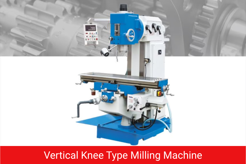
The underlying formulas stay the same, but the machine’s rigidity and spindle orientation shape practical limits. A Horizontal Milling Machine, with its spindle axis parallel to the table, often distributes cutting forces differently and can support heavier stock removal with side-and-face cutters. A Vertical Milling Machine, more common for general-purpose work, is typically set up with end mills and face mills where axial depth of cut is the primary control.
How does a Turret Milling Machine influence feed and speed choices?
On a Turret Milling Machine, the head itself can tilt and swivel, which is useful for angled cuts but can introduce additional flex if the head isn’t locked correctly. Operators usually run slightly conservative feed rates on turret setups compared to fixed-head machines, especially when the head is positioned away from center.
Why speed and feed rate calculations different on a CNC Milling Machine?
A CNC Milling Machine follows identical formulas, but the control system executes them with far greater consistency than manual handwheel feeding. Many CNC controllers include built-in calculators or accept direct RPM and feed rate values in the program and some allow real-time feed override during the cut. The main difference is precision and repeatability rather than the math itself.
Our Other Product
Cylindrical Grinding MachinesWhy Light Duty and Heavy Duty Milling Machine use the same chip load charts?
The chip load charts are the same starting reference, but a Light Duty Milling Machine usually has less spindle horsepower and a lighter frame, so operators often stay toward the lower end of the recommended chip load range. A Heavy Duty Milling Machine, built for continuous stock removal, can often run toward the upper end of the same chart without sacrificing tool life.
How to Calculate Optimal Settings Step by Step
- Identify the workpiece material and look up its recommended SFM (or SMM) range for the tooling being used – carbide, HSS or coated tooling each have different ranges.
- Measure the cutting tool diameter accurately, since even small errors here shift RPM calculations noticeably.
- Calculate RPM using the SFM formula, then round to a setting the machine’s spindle can actually achieve.
- Select a chip load value appropriate to the tool diameter and material from a manufacturer’s reference chart.
- Calculate feed rate by multiplying RPM, number of flutes and chip load per tooth.
- Set depth of cut based on the machine’s rigidity – lighter passes for benchtop or Light Duty Milling Machine setups, deeper roughing passes for a Heavy Duty Milling Machine.
- Run a test pass and listen and watch for chatter, excessive heat or poor chip formation, then adjust feed rate incrementally rather than spindle speed first.
- Fine-tune for finish or productivity depending on whether the operation is a roughing pass or a final finishing pass.
How Do You Adjust Speed and Feed for Different Work Materials?
Material hardness and thermal conductivity are the two biggest variables. Aluminum and other non-ferrous metals conduct heat away from the cutting edge quickly, which allows higher SFM values and generally more aggressive feed rates. Steel alloys generate more heat at the cutting zone, so SFM drops and feed rates need to be paired carefully with coolant flow to prevent built-up edge and premature tool wear. Cast iron behaves differently again – it’s abrasive rather than gummy, so tool life becomes the limiting factor more than heat and moderate SFM with steady feed usually performs best. Stainless steel work-hardens quickly if feed rate is too light, so machinists often favor a slightly heavier chip load to keep the cutting edge engaged rather than rubbing.
What Mistakes Do Machinists Commonly Make with Speed and Feed Calculations?
The most frequent error is treating chip load charts as fixed rules rather than starting points – every setup has some deflection, some spindle runout and some variation in workholding rigidity that the chart can’t account for. Another common mistake is adjusting spindle speed to fix chatter when the actual fix is usually feed rate or depth of cut. Running a Vertical or Horizontal Milling Machine at the theoretical maximum RPM without accounting for tool overhang is another frequent cause of premature tool failure, since longer overhang always reduces the practical maximum feed rate regardless of what the formula suggests.
Bhavya Machine Tools has spent years supplying workshop and metalworking machinery to manufacturers across India and international markets, including operations in the UAE and the USA. Its product range spans lathe machines, drilling machines, grinding machines and a wide selection of milling machines, alongside metal fabrication equipment such as press brakes, shearing machines and laser cutting systems. Clients across automotive, aerospace, construction and general manufacturing rely on Bhavya’s engineering support and after-sales service to keep machining operations running with consistent accuracy and uptime.
Read Our Article
Global Demand of Slotting MachineConclusion
Getting speed and feed rate right on a milling machine comes down to a handful of dependable formulas, applied with attention to the specific machine, tool and material in front of you. Whether the setup involves a Vertical Milling Machine for general shop work, a Horizontal Milling Machine for heavier stock removal, a Turret Milling Machine for angled cuts or a CNC Milling Machine running an automated program, the same fundamentals of RPM, chip load and depth of cut apply. Building the habit of calculating these values before every job – rather than relying on memory or guesswork – is what separates consistent, tool-friendly machining from costly trial and error.
FAQs
Milling Machine Speed and Feed Rate Calculator: A Practical Guide for Machinists
What is the difference between surface speed and feed rate?
Surface speed (SFM/SMM) describes how fast the cutting edge moves through the material, while feed rate describes how quickly the workpiece or tool advances during the cut.
Can I use the same speed and feed calculator for both manual and CNC milling machines?
Yes, the formulas for RPM and feed rate are identical; only the method of applying them - manual handwheel versus programmed motion - differs.
Why does chip load matter more than just spindle speed?
Chip load determines how much material each cutting edge removes per pass, which directly affects tool wear, heat generation and surface finish, regardless of how fast the spindle is turning.
Do smaller milling machines require lower feed rates?
Generally yes - a Light Duty Milling Machine has less rigidity and horsepower than a Heavy Duty Milling Machine, so feed rates are usually kept toward the conservative end of the chip load chart.
How often should speed and feed settings be recalculated?
Settings should be reviewed whenever the tool diameter, material or number of flutes changes and rechecked periodically as tools wear, since a dulling edge often needs a reduced feed rate to maintain finish quality.