CNC Panel Bending Machine Process: From CAD File to Finished Product
Modern sheet metal fabrication has undergone a dramatic transformation with the integration of digital control systems. The CNC Panel Bending Machine represents the pinnacle of this evolution – a precision-driven, software-coordinated system that translates a digital design into a finished metal component with minimal human intervention. Unlike conventional press brakes that rely heavily on operator skill and manual setup, these machines execute complex forming sequences with repeatable accuracy, making them the go-to solution for high-volume and high-precision production environments.
Understanding the complete workflow – from the moment a CAD file is generated to the moment a part exits the machine – reveals just how precisely engineered this process is. Each stage is tightly controlled and the interaction between software, mechanics and material science is what defines modern panel bending.
 Email Us Today!
CNC Panel Bending Machine: How Digital Design Becomes Machine Instructions
Everything begins in a CAD (Computer-Aided Design) environment. Engineers draw the flat sheet metal part and define all bend lines, bend angles, flange lengths and tolerances. This file is then imported into CAM (Computer-Aided Manufacturing) software specifically designed for sheet metal processing.
The CAM software analyzes the 3D model and automatically generates a bending sequence. It calculates the optimal order of bends to avoid tool collisions, selects the correct tooling profiles and determines the precise positioning movements the CNC Bending Machine must execute. Once the program is validated in simulation, it is transferred to the machine controller via a network connection or USB interface.
At the controller, the operator verifies the program parameters – material type, sheet thickness, alloy grade and surface finish requirements – before authorizing the run. This digital handshake between design intent and machine execution is what gives the CNC Panel Bending Machine its defining advantage: human error in setup is effectively eliminated because the machine reads and interprets the part program directly.
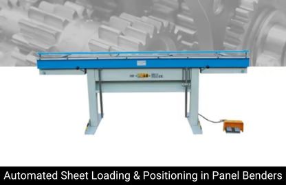
Panel Benders: Sheet Loading and Automatic Positioning
Once the program is ready, the physical process begins with sheet loading. On most Panel Benders, this is handled by an integrated loading system – typically a vacuum cup or magnetic gripper mechanism – that picks a sheet from a stack and places it onto the machine’s measuring and positioning table.
The sheet is automatically aligned against reference stops, which confirm its exact position using encoder feedback. The positioning system accounts for sheet size tolerances and ensures that the first bend begins from an accurately known reference point. In high-throughput configurations, this loading step is part of a continuous automated cycle, with the machine pulling sheets from a pallet or magazine without operator assistance between parts.
The precision of this step is critical. Any misalignment in sheet positioning at this stage will propagate through every subsequent bend, resulting in dimensional errors that compound across the part. The positioning system on a well-engineered Automatic Panel Bender achieves positional accuracy in the range of ±0.1 mm, which is essential when working to tight engineering tolerances.
Automatic Panel Bender: The Bending Sequence Executed in Detail
The actual bending process is where the Automatic Panel Bender distinguishes itself from conventional machinery. Unlike a press brake, which presses a punch into a die to form a bend, a panel bender uses a pair of upper and lower bending tools – called the bending beam – that move in a coordinated arc around the clamping area.
The process for each bend follows this sequence: The blank holder clamps the sheet firmly at the bend line. The bending beam then moves upward or downward (or both in sequence for hem bends and complex profiles) to form the flange to the specified angle. The Automatic Panel Bender machine’s controller monitors real-time feedback from angle-measuring sensors – either integrated into the tooling or positioned on the bending beam – and makes micro-corrections to achieve the exact programmed angle. After each bend, the backgauge repositions the sheet for the next bend line with servo-driven precision.
On machines equipped with an angle correction system, the controller compensates for springback automatically. Springback is the elastic recovery of the metal after forming and its magnitude varies with material type, thickness and temper. Rather than requiring the operator to calculate an overbend angle manually, the Automatic CNC Metal Sheet Panel Bender measures the actual formed angle mid-cycle and adjusts its motion in real time. This feedback loop is essential for maintaining consistent part geometry across long production runs involving variable material batches.
Flexible Panel Bender: Handling Complex Geometries and Multi-Flange Parts
One of the most technically significant aspects of the Flexible Panel Bender is its ability to produce parts with multiple bends, closed profiles and varying flange lengths without retooling. Conventional press brakes require tool changes and multiple setups to achieve this; a panel bender handles it within a single automated cycle.
For a part with four flanges – for instance, a rectangular enclosure panel – the Flexible Panel Bender works through the bend sequence as programmed, rotating and repositioning the sheet between each bend. The rotational movement is carried out by an integrated sheet manipulator, which grips the part and pivots it to the next required orientation. This rotation is programmed in the CAM file and executed under servo control, maintaining positional accuracy throughout.
The flexibility of this approach extends to producing positive and negative bends on the same part without flipping the sheet manually. The bending beam can engage from above or below and some machines use an additional follower tool that supports the already-formed flanges during subsequent bends to prevent deformation. This capability is what makes the Flexible Panel Bender particularly well-suited to HVAC panels, electrical enclosures, elevator cab components and architectural cladding – all products that demand complex profiles formed from a single flat blank.
CNC Panel Bender Machine: Material Flow and In-Process Quality Control
Throughout the bending cycle, the CNC Panel Bender Machine continuously monitors several process parameters. Force sensors embedded in the bending beam detect resistance from the material and compare it against expected values for the specified sheet thickness and grade. Deviations can indicate a wrong material being loaded, a thickness variation in the coil stock or a hardness inconsistency – any of which could affect final part dimensions.
Angle measurement systems, which may use laser triangulation or tactile probes depending on the machine design, verify the actual formed angle at each step. If an angle falls outside tolerance, the machine either corrects the overbend or flags the part for inspection before it advances to the next bend. This in-process quality control reduces scrap rates significantly compared to systems that rely on post-production inspection.
Modern Panel Benders also track production data at the part level. The controller logs the date, time, program name, material batch and measured angles for each component. This data can be exported to a manufacturing execution system (MES) for traceability purposes – an increasingly important requirement in sectors such as aerospace components, medical device housings and industrial control panels, where part-level documentation is mandatory.
What Our Customers Say
“Largest Display of Machinery across India. Wide range of Machines. Very Co-operative staff. Range of Tapping Machine and Re-sharpening Machines are outstanding. Very Cost effective and useful in Precision Machining Work. Their staff is co – operative for after sales support.”
Tirth Bhojani On Google
Panel Bender Manufacturer: How Machine Design Influences Process Capability
The process outcomes described above are directly influenced by the engineering design choices made by the Panel Bender Manufacturer. Frame rigidity, drive system architecture, tooling geometry and control software all determine the machine’s effective process capability.
A rigid machine frame – typically fabricated from high-grade cast iron or welded steel with finite-element-optimized profiles – ensures that deflection under load remains below the threshold that would affect bending accuracy. Servo-driven axes with ball screw or linear motor actuation provide the positioning repeatability required for tight-tolerance work. The quality and design of the bending tools themselves determine how cleanly the material is formed – poorly designed tools introduce surface marks, incorrect radii or uneven stress distribution across the bend zone.
Control software from a competent Panel Bender Manufacturer goes beyond simple motion control. It integrates material databases, springback compensation algorithms, collision avoidance logic and real-time process monitoring into a unified platform. This software layer is often where differentiation between machines becomes most apparent – it defines how intelligently the machine responds to variations in material and process conditions during production.
CNC Bending Machine: Part Unloading, Stacking and Final Inspection
Once all bends have been completed, the finished part is transferred to the unloading area. On fully automated lines, a robotic arm or a programmed unloading conveyor removes the part and places it on a stacking station, where parts are layered with protective interleaving material to prevent surface damage.
The CNC Bending Machine’s unloading sequence is programmed to account for the part’s final geometry – a closed box profile, for instance, requires a specific removal path to avoid interference with the machine’s tooling. The controller manages this path automatically, ensuring consistent and damage-free unloading even for complex formed shapes.
Post-process inspection for panel bent parts typically focuses on flange length measurements, overall part flatness, angle accuracy and hole position relative to bend lines. Coordinate measuring machines (CMMs) or optical measurement systems are used in quality labs to verify first-article approval. For ongoing production, statistical sampling with manual gauges or go/no-go fixtures is common, supported by the machine’s own data logs as a process audit trail.
Conclusion
The entire workflow – from CAD file import through material loading, bend execution, in-process angle correction and finished part unloading – represents a tightly integrated process chain. Each step is governed by digital control, embedded in the machine’s software and mechanical precision designed into every component. The result is a forming process that delivers consistent, high-accuracy sheet metal parts at production speeds that manual methods cannot approach, making the CNC Panel Bending Machine an essential asset in advanced fabrication operations worldwide.


